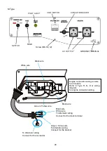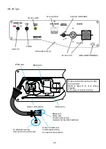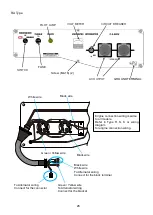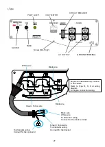
3-2. REMOVAL
3.2.1 CONTROL PANEL AND CONTROL BOX
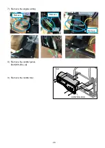
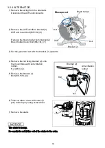
1) Remove the end cover.
Bolt (M5-12L) (2).
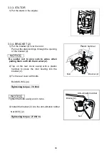
2) Remove the wiring from the control panel to
the alternator.
3) Remove the Black wire and White
wire from terminal block.
4) Remove the Green/Yellow wire from
bracket (2).
Bolt (M5-12L) (1)
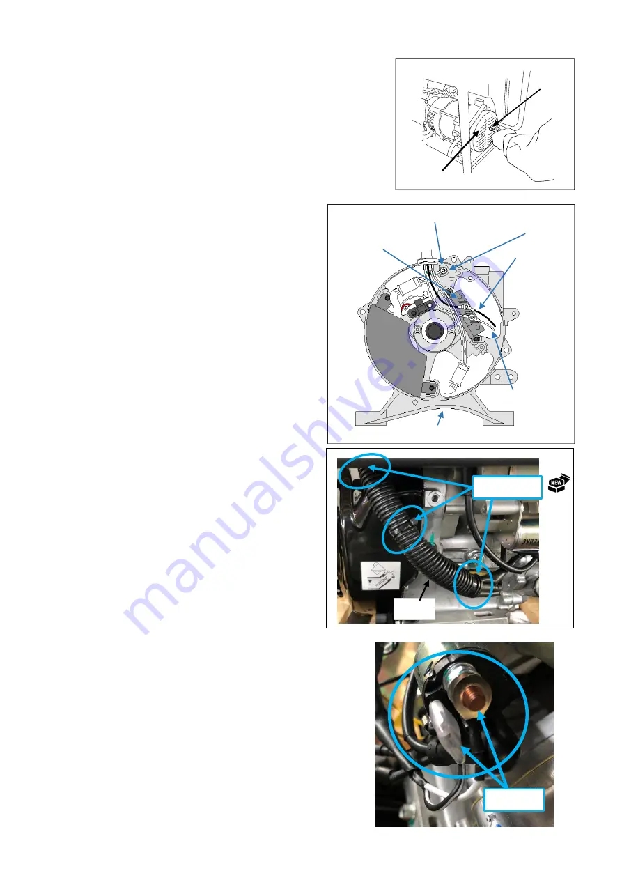
5) Cut the wire band.
Remove the tube.
Wire band can not be reused.
Replace with new.
6) Remove the cell motor wiring.
Remove
End cover
Bolt
Wire band
Tube
Green/Yellow wire
Black wire
White wire
Terminal
block
Bracket (2)
Bolt
18
19
Summary of Contents for EZ6500CXS
Page 1: ......
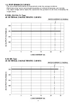
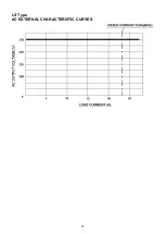
Page 10: ...L LB Type AC EXTERNAL CHARACTERISTIC CURVES S SB Type AC EXTERNAL CHARACTERISTIC CURVES 10 ...
Page 11: ...LS Type AC EXTERNAL CHARACTERISTIC CURVES 11 ...
Page 44: ...4 4 ALTERNATING CURRENT VOLTAGE IS OV 44 ...
Page 51: ...4 11 WIRING DIAGRAM R S K Type 51 ...
Page 52: ...RK LS MK Type 52 ...
Page 53: ...REH CL Type 53 ...
Page 54: ...M Type 54 ...
Page 55: ...SB LB Type 55 ...
Page 56: ...L Type 56 ...
Page 57: ...62EAB00 2019 Sep ...

