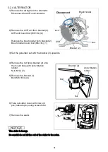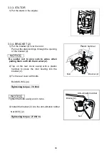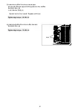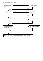
3.2.4 ALTERNATOR
1) Remove the wiring from the alternator.
Disconnect the AVR unit connector.
2) Remove the AVR unit from bracket (2).
AVR unit mount bolt (M5-16L) (2)
Remove the brush holder from bracket (2)
Brush holder mount bolt (M5-16L) (1)
3) Set the generator set with the bracket (2) upwards.
4) Remove the nut fixing bracket (2) onto
the mount base with anti-vibration
rubber.
Nut (M10) (2).
5) Remove the bracket (1).
Bolt (M6-165L) (4)
6) Take out stator cover with crows (2
pcs) raised up by using screw driver.
7) Remove the stator.
The stator is heavy.
Be careful do not hit the coil of the stator to the rotor.
Disconnect
Brush holder
AVR
Bracket (2)
Bolt
Bolt
Bracket (2)
Bolt
Nut
Anti-vibration
rubber
31
Summary of Contents for EZ6500CXS
Page 1: ......
Page 10: ...L LB Type AC EXTERNAL CHARACTERISTIC CURVES S SB Type AC EXTERNAL CHARACTERISTIC CURVES 10 ...
Page 11: ...LS Type AC EXTERNAL CHARACTERISTIC CURVES 11 ...
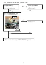
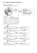
Page 44: ...4 4 ALTERNATING CURRENT VOLTAGE IS OV 44 ...
Page 51: ...4 11 WIRING DIAGRAM R S K Type 51 ...
Page 52: ...RK LS MK Type 52 ...
Page 53: ...REH CL Type 53 ...
Page 54: ...M Type 54 ...
Page 55: ...SB LB Type 55 ...
Page 56: ...L Type 56 ...
Page 57: ...62EAB00 2019 Sep ...


