3-3. INSTALLATION
3.3.1. ENGINE AND FRAME
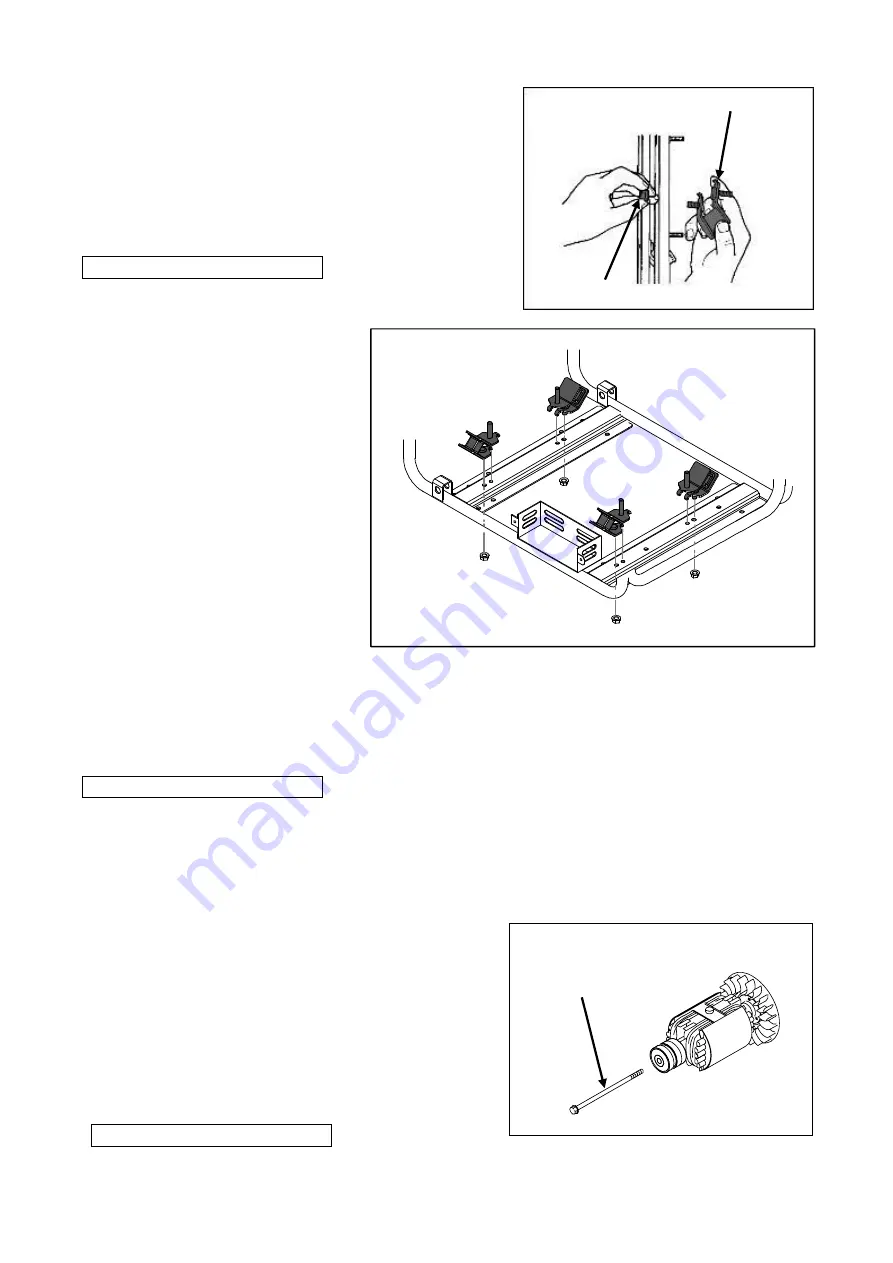
1) Install the anti-vibration rubbers to the frame.
Insert the setting tongue of anti-vibration
rubbers into the hole on the frame and tighten
the nut from the bottom of the frame.
Nut (M8) (4)
Tightening torque: 15.0
N•m
2) Install the engine into the frame from the side of it.
Tighten the nuts over the anti-vibration rubber
bolts to fix.
Nut (M10)
(2)
Tightening torque: 27.0
N•m
3.3.2. ROTOR
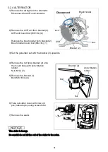
1) Wipe off oil, grease and dust from the tapered
portion of engine shaft and matching tapered
hole of rotor shaft.
2) Mount the rotor to the engine shaft.
Tighten the Generator rotor bolt.
Generator rotor bolt (M10 × 275L) (1)
Tightening torque: 45.0
N•m
Anti-vibration rubber
Nut (M8)
Generator rotor bolt
33
Summary of Contents for EZ6500CXS
Page 1: ......
Page 10: ...L LB Type AC EXTERNAL CHARACTERISTIC CURVES S SB Type AC EXTERNAL CHARACTERISTIC CURVES 10 ...
Page 11: ...LS Type AC EXTERNAL CHARACTERISTIC CURVES 11 ...
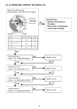
Page 44: ...4 4 ALTERNATING CURRENT VOLTAGE IS OV 44 ...
Page 51: ...4 11 WIRING DIAGRAM R S K Type 51 ...
Page 52: ...RK LS MK Type 52 ...
Page 53: ...REH CL Type 53 ...
Page 54: ...M Type 54 ...
Page 55: ...SB LB Type 55 ...
Page 56: ...L Type 56 ...
Page 57: ...62EAB00 2019 Sep ...


