Date of Issue: February, 2005
© American Honda Motor Co., Inc.
3-7
FG110
6. VALVE CLEARANCE
ADJUSTMENT
Valve clearance inspection and adjustment must be
performed with the engine cold.
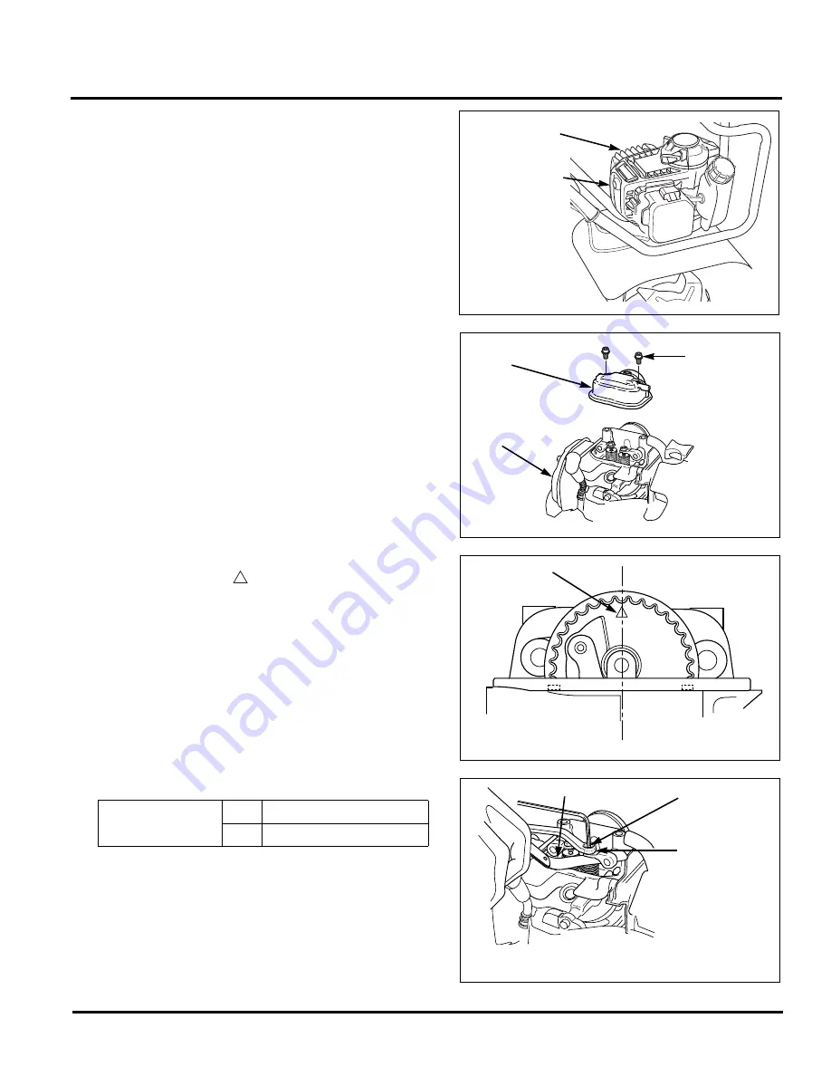
1. Remove the 5 x 12 mm hex bolt and remove the top cover.
2. Remove the two 5 x 12 mm hex bolts from the head cover.
Engine oil can leak out when removing the head cover.
Catch the leaking oil with a suitable material and wipe up
the area immediately.
3. Set the piston at top dead center of the compression
stroke by aligning the “
“ mark on the cam pulley with
the cylinder head center.
4. Insert a feeler gauge between the rocker arm and valve to
measure the valve clearance.
5. If adjustment is necessary:
a. Loosen the adjusting screw lock nut and turn the
adjusting screw right or left.
b. Hold the adjusting screw with the tappet adjusting
wrench and tighten the lock nut to the specification.
Torque: 4.9 N•m (0.5 kgf•m, 3.9 lbf•ft)
c. Recheck the valve clearance.
Standard valve
clearance
IN
0.08 ± 0.02 mm
EX
0.11 ± 0.02 mm
5 x 12 mm
HEX BOLT
TOP
COVER
5 x 12 mm
HEX BOLT (2)
HEAD COVER
ENGINE
ASSEMBLY
ALIGNMENT
MARK
CYLINDER HEAD CENTER
ADJUSTING
SCREW
ADJUSTING
SCREW
LOCK NUT
FEELER GAUGE
To increase valve clearance, screw out.
To decrease valve clearance, screw in.
Summary of Contents for FG110
Page 3: ...Date of Issue February 2005 American Honda Motor Co Inc...
Page 7: ...Date of Issue February 2005 1 4 American Honda Motor Co Inc FG110 NOTES...
Page 35: ...Date of Issue February 2005 4 6 American Honda Motor Co Inc FG110 NOTES...
Page 79: ...Date of Issue February 2005 11 4 American Honda Motor Co Inc FG110...


