background image

SAFETY LABEL LOCATIONS 

SAFETY LABEL LOCATIONS 

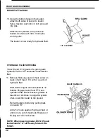
Read these SAFETY LABELS before you operate the front loader. 

IMPROPER 

SERVICING 

CAN  CAUSE 

SERIOUS INJURY OR DEATH 

lower loader to the ground and 

shut off engine. 

disconnecting oil lines. 

Before 

servicing or adjustment 

Rolleve  hydraulic 

pressure 

before 

LOADS  CAN 

FALL  FROM 

BUCKET 

CAUSING  SERIOUS  INJURY  OR  DEATH 

TRACTOR TIP-OVER CAN 
CAUSE SERIOUS INJURY 

OR 

DEATH 


A

dd 

recommended 

wheel ballast and/or 

counterweights for 

stability.

Drive and turn

tractor at slow speed.

Place loader 

low when

transporting 

loads, 

especially on an incline 

or rough terrain. 

Put loader on ground 

when parked. 

Read and understand 

all instructlons in

operator's manual 

before 

operation. 

INFORMATION 

Special loader attachments 

for 

handling large objects are 
available from agricultural 
suppliers. 

Summary of Contents for FL5540KO

Page 1: ...40PERATOR S A MANUAL J Front Loader Model FL5540KO for Honda H5518A4 Multi purposeTractor I...

Page 2: ......

Page 3: ...N 10 5 LOADER SPECIFICATIONS 11 6 ASSEMBLY INFORMATION 12 Sub frame installation removal 13 Front loader assembly 19 Operational checks 25 7 OPERATING INSTRUCTIONS 27 8 LOADER REMOVAL 31 Storage 35 9...

Page 4: ...at extra cost The manufacturer reserves the right to redesign and change the machine as may benecessary without notification NOTE Illustrations used in this manual may not show all safety equipment th...

Page 5: ...en modified or structurally damaged Know how to stop the engine quickly Thoroughly understandoperation of all controls Never permit anyone to operate the tractor or front loaderwithout properinstructi...

Page 6: ......

Page 7: ...g the front loader on sloping or uneven surfaces Operate loader controls only from the operator s seat to prevent possible severe personal injury Attempting to change gears while operating the front l...

Page 8: ...ying metal objects Operating the front loader or the tractor with damaged worn or broken parts may result in severe personal injury Before disconnecting any hydraulic lines relieve all hydraulic press...

Page 9: ...FALL FROM BUCKET CAUSING SERIOUS INJURY OR DEATH TRACTOR TIP OVER CAN CAUSE SERIOUS INJURY OR DEATH Add recommended wheel ballast and or counterweights for stability Drive and turn tractor at slow sp...

Page 10: ...PACKAGINGINVENTORY PACKAGINGINVENTORY I3 I 12 Required 37 5 Ibs each j 1 WEIGHTS SECUREDTO CRATE BOTTOM I CIC c I l l l l l l i LARGE CARTON SMALL CARTON 1...

Page 11: ...ctor Weight added to the rear of the tractor provides better traction and easier more efficient loader operation The tractor must be counterweighted by installation of rear weights Additional counterw...

Page 12: ...Maximum Height Reachwhucket on ground Maximum Dumpangle Digging Depth Below Grade Tractor Type H55 Maximum Lift Height Bucket roll back angle A FL5540 400lb 180kg 42in 1050mm Double acting Suit caset...

Page 13: ...e values of hardware required for assembly Lay out and identify all components prior to installation TORQUE SPECIFICATIONS AMERICAN Bolt HeadMarkings SAE Grade2 No Dashes SAE Grade5 3 Dashes METRIC 6...

Page 14: ...t lbs 39 Nm TORQUE 3 TIGHTEN UNDERSIDE MOUNTING BOLTS 29 ft lbs 39 Nm TORQUE NEW LOWER FRONTCOVER m THE TRACTOR FRAME CAN BE DAMAGED IF THE TRACTOR IS MOVED WHILE THIS COVER IS OFF OR BOLTS ARE NOT TI...

Page 15: ...n line with the sub frameandtireguide ondrive onplate allowing a clearance of approximately 60mm 2 4in between sub frame and the innerwall of the left front tire 5 Drive the tractor the rear of the su...

Page 16: ...OVAL 6 Stop the tractor when the mast fixing pad comes even with the floor board ofthe tractor 7 Using two people lift the sub frame and engage the pipe ofsub frame into the U shapedchannel of the bot...

Page 17: ...lower cover Slip a 3 4in washer over each mounting pin and insert the clip pins through the holes NOTE Mounting pins have a flat side that must be pointing down 9 Insert two mounting pins 3 4 x 3 19in...

Page 18: ...igning the mounting holes of the bracket with those of the sub frame Insert two 1 x 3 5inch mounting pins in the forward holes and one 1 x 12 inch mounting pin in rear lower hole Secure with linchpins...

Page 19: ...oating ofgrease to tractor front PTO at this time Mount hydraulic pump to tractor by sliding splined pump drive joint onto front PTO shaft with mounting brackets inside main frame and attaching with f...

Page 20: ...nd on the pump Attach with hose clamps and tighten securely 5 Attach the front guard on the front ofthe sub frame using two each 1 2 x 1 inch and 1 2 x 15 16 inch bolts and four each 1 2 inch nuts and...

Page 21: ...ft brace arm with metal loops Ensure that the high pressure hose smaller diameter is positioned on top of the suction hose large diameter Install the nylon tie strap to bind the two hoses together at...

Page 22: ...utomatic transmission fluid 11 Remove filler plug and oil check screw on back of left mast Fill with 4 quarts of hydraulic fluid Start tractor engine and set speed at 1 2 throttle Engage tractor front...

Page 23: ...e the stands 14 Align the hole in the bottom of the stand with the mounting hook at rear of mainframe Slide the stand over the mounting hook and then insert the latch pin previously removed through ma...

Page 24: ...or meets all requirements in Tractor Preparation Section Check front loader hydraulic fluid level Refer to front loader operator s manual Note Bucket and lift cylinders should be fully retracted when...

Page 25: ...ts of a piece of machinery If its ability to do a job or to do so safely is in question Don t try it Don t hurry the learning process or take the unit for granted Ease into it and become familiar with...

Page 26: ...A Righthandle pushed all the way forward this is float position Handle will stay until pulled back POSITION B Right handle pushed half way forward bucket will lower POSITION C Neutral position POSITIO...

Page 27: ...oat Position B Loader Down C Neutral D Loader Up B Neutral C Bucket Back SCRAPING When scraping the float position should be utilized to maintain the bucket firmly on the ground and at the same time a...

Page 28: ...capacity This procedure also results in the material being removed in layers from the top for maximum loading efficiency When the bucket is full raise loader so that the bucket is clear of material a...

Page 29: ...ound is irregular Make turns slowly and use the tractor brakes cautiously A full bucket in the raised position alters the center of gravity of the unit and increases the possibility of mishaps 1 Do no...

Page 30: ...l Lower bucket to the ground and remove the stands from the loader main frame 2 Raise the loader until the stands can be inserted into the loader arms Install the clip pins into the stand ends 3 Lower...

Page 31: ...ket operation to make fixing pin removal easier 5 Remove the clip pins and mounting pins from the masts and the front guard Remove the hydraulic hoses from the left brace loops Remove the brace arms 6...

Page 32: ...he front guard from sub frame 8 Remove the hydraulic pump by removing the four bolts holding the mounting brackets to the tractor frame Remove the pump from the PTO shaft NOTE Do not disconnect hoses...

Page 33: ...on or around the tractor or loader PROCEDURES BEGINNINGOFSEASON 1 Review safety precautions and operation sections of manual 2 Thoroughly clean loader of all accumulated dirt and grease 3 If removed...

Page 34: ...ove the tractor centrally between the masts 2 Mount hydraulic pump to tractor by sliding splined pump drive joint onto front PTO shaft with mounting brackets inside main frame and attaching with four...

Page 35: ...s onto the pads 5 Use bucket movement to shake masts to align pin holes Insert the fixing pins through the masts and pads Install clip pins through holes 6 Attach brace arms to mast and front guard as...

Page 36: ...m the stands and 9 Align the hole in the bottom of the stand with the mounting hook at rear of mainframe Slide the stand over the mounting hook and then insert the fixing pin previously removed throug...

Page 37: ...il Oil viscosity may be too high at start Before operating allow oil to warm up Components sticking or binding Check for dirt or gummy deposits Pump damaged Check for worn or broken parts SYSTEM RUNS...

Page 38: ...WITH CONTROL VALVE IN NEUTRALPOSITION Leaking or broken oil lines from control valves to cylinder Check for leaks Tighten or replace lines Oil leaking past cylinder packing or O rings Replace worn par...

Page 39: ...Note If oil seepage past cylinder rod is evident look for scoring on rod Tractor tire inflation should be checked as listed in tractor owner s manual to ensure tire inflation is to specification Uneq...

Page 40: ...on Check Weekly 50 Hrs Loader pivot points Lubricate Daily 10 Hrs Hydraulic lines hoses Checkfor leakage Daily 10 Hrs andconnections wear and damage Lift and bucket cylinders Checkfor seepage Daily 10...

Page 41: ...PIPE NIPPLE 1 2x 45 PIPE ELBOW 1 2 PIPE END 3 8 90 ST ELBOW 3 8 x 3 PIPE NIPPLE 3 8 90 PIPE ELBOW 3 4 SUCTION HOSE 16 HOSE CLAMP 1 2 3 8 HEX REDUCER BUSHING 3 8 x 60 HYDRAULICHOSE9 16 18 ORB x 3 8MS...

Page 42: ...46...

Page 43: ...LIC HOSE 9 16 18 ORBx3 8 MJlC 3 8 x 20 HYDRAULIC HOSE 9 16 18 ORB x3 8MS 1 4 x 16 HYDRAULIC HOSE 1 4 MP x318 MJIC 1 2 x 90 ST ELBOW 1 2 VENT PLUG 1 2 PIPE END 3 8 x 90 ST ELBOW 1 4 x 90 ST ELBOW 10 X...

Page 44: ...CKETA 2 PIN COUNTERWEIGHTBRACKET B PIN COUNTERWEIGHTBRACKETC 2 1 PIN D WITH FLAT Mounting Pin 4 PINE Fixing Pin 4 5 8 x 1 1 4 LEVIS PIN 4 7 1 6 LYNCH PIN 5 11 CLIP PIN 12 1 1 4 x 314 x 10ga MACHINERY...

Page 45: ...2 9 SPACER 1 10 DETENTSPOOL 1 11 RETURNSPRING 1 12 DETENTPLUG 2 13 DETENTSPRING 2 14 STEEL BALL 2 15 DETENTENDCAP 1 16 LOADCHECK POPPET 1 17 LOAD MCHECK PLUG 2 18 LOADCHECK SPRING 1 19 TAMPER PROOFCA...

Page 46: ...isfaction contact the Power Equipment Customer Relations Department of American Honda Motor Co Inc American Honda Motor Co Inc Power Equipment Customer Relations Department P O Box 10021 Duluth Georgi...

Page 47: ...is way If you are dissatisfied with the decision made by the dealership s management contact the Honda Power Equipment Customer Relations Office You can write American Honda Motor Co Inc Power Equipme...

Page 48: ......

Reviews: