7-4
dummyhead
dummyhead
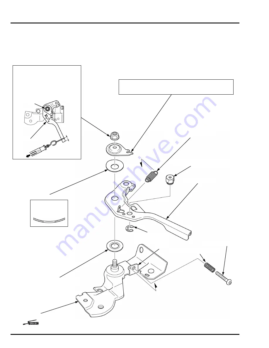
GOVERNOR SYSTEM
CONTROL BASE
DISASSEMBLY/ASSEMBLY
REMOTE TYPE
Remove the control base (page 7-3).
INSTALLATION:
After installation the control base Assy.,
measure force at 10 mm (0.4 in) from
the tip of the control lever [1] by pulling.
Adjust by turning the lock nut [2] so that
the gauge shows 19.6 ± 4.9 N (2.0 ±
0.5 kgf) when the control lever starts to
move.
CONTROL LEVER WASHER
CONTROL LEVER
CONTROL BASE
CONTROL LEVER SPACER
CLAW
LOCK NUT (6 mm)
INSTALLATION:
Install the control lever washer by aligning the cutout of the control
lever washer with the claw of the control base.
CABLE RETURN SPRING
INSTALLATION:
Note the installation
direction.
(Control lever sliding surface)
LEVER SPRING
[1]
[2]
10 mm
(0.4 in)
SCREW (5 x 25 mm)
CONTROL ADJUST SPRING
WIRE HOLDER (Except QX3 type)
CIRCLIP
(Except QX3 type)
Summary of Contents for GP160H
Page 19: ...MEMO dummyhead dummyhead ...
Page 26: ...2 7 dummyhead dummyhead SERVICE INFORMATION Valve guide reamer 5 510 mm 07984 2000001 ...
Page 28: ...2 9 dummyhead dummyhead SERVICE INFORMATION FUEL TUBE BREATHER TUBE HIGH TENSION CORD ...
Page 39: ...MEMO dummyhead dummyhead ...
Page 40: ...4 1 4 dummytext 4 TROUBLESHOOTING BEFORE TROUBLESHOOTING 4 2 TROUBLESHOOTING 4 2 ...
Page 45: ...MEMO dummyhead dummyhead ...
Page 46: ...5 1 5 dummytext 5 FAN COVER FAN COVER REMOVAL INSTALLATION 5 2 ...
Page 49: ...6 2 dummyhead dummyhead FUEL SYSTEM FUEL SYSTEM TOOL Float level gauge 07401 0010000 ...
Page 57: ...MEMO dummyhead dummyhead ...
Page 65: ...MEMO dummyhead dummyhead ...
Page 73: ...MEMO dummyhead dummyhead ...
Page 87: ...MEMO dummyhead dummyhead ...
Page 97: ...MEMO dummyhead dummyhead ...
Page 111: ...MEMO dummyhead dummyhead ...
Page 112: ...14 1 14 dummytext 14 WIRING DIAGRAMS WIRING DIAGRAMS 14 2 ...


