background image

1-21

GX120K1•GX160K1•GX200

SPECIFICATIONS

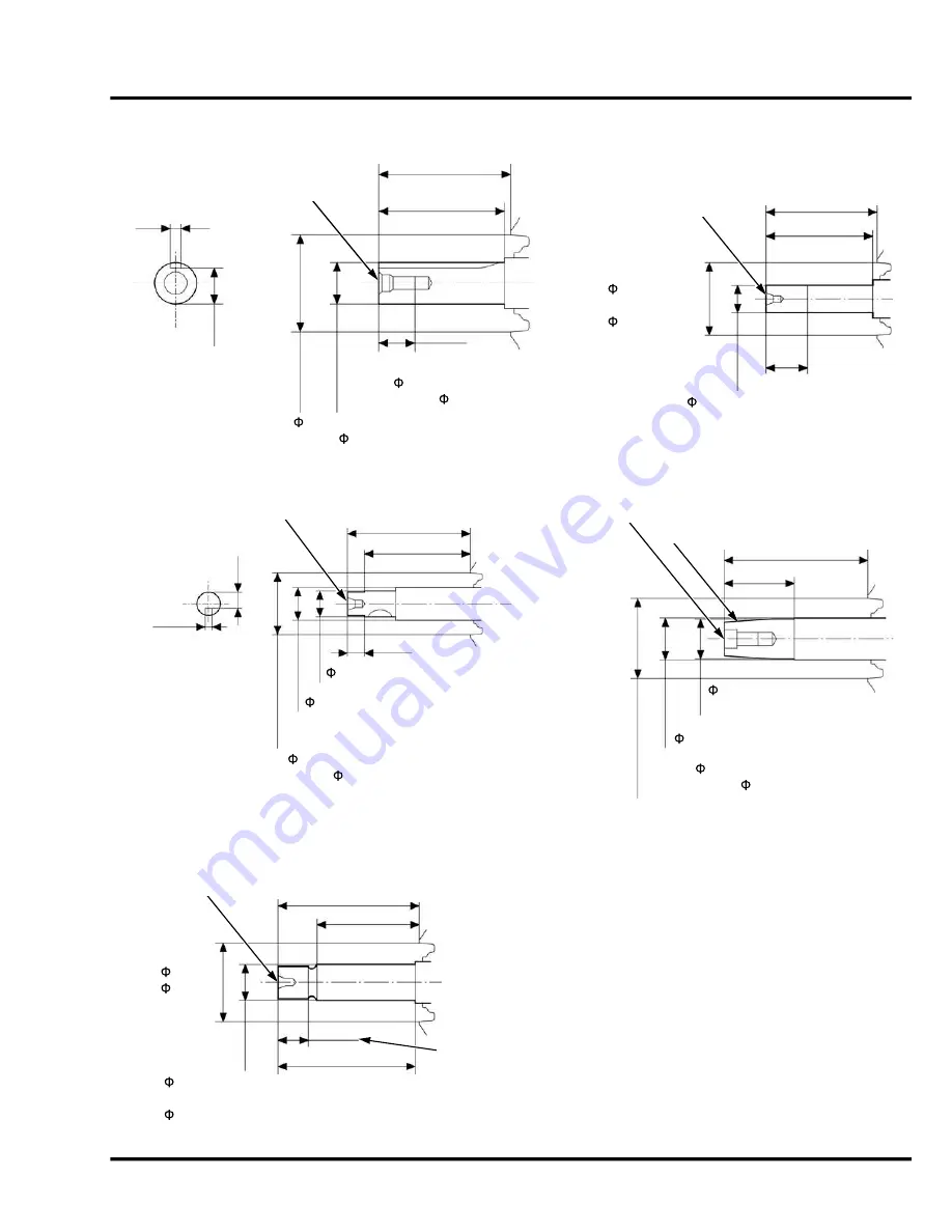
 15.852 – 15.870 (0.6241 – 0.6248)

Unit: mm (in)

61.7 (2.43)

GX120:

 78 (3.1)

GX160/GX200:

 74 (2.9)

58.5 (2.30)

S type*

T type*

Unit: mm (in)

22.5 (0.89)

5/8-18UNF-2ARH

M8 X 1.25

53.2 (2.09)

50 (2.0)

23 (0.9)

GX120:   17.957 – 17.984 (0.7070 – 0.7080)

GX160/GX200:   19.947 – 19.980 (0.7853 – 0.7866)

GX120: 14.90 – 15.00

(0.587 – 0.591)

GX160/GX200: 16.90 – 17.00

(0.665 – 0.669)

5.00 – 5.03 

(0.197 – 0.198)

GX120:   78 (3.1)

GX160/GX200:   74 (2.9)

 18.927 – 19.177

(0.7452 – 0.7550)

71.7 (2.82)

Unit: mm (in)

U type*

V type*

Unit: mm (in)

5/16-24UNF-2B

TAPER 2-1/4

33.5 (1.32)

 19.830 – 19.843 (0.7807 – 0.7812)

 14.225 – 14.275 (0.5600 – 0.5620)

 19.000 – 19.050 (0.7480 – 0.7500)

8 (0.3)

66 (2.6)

56 (2.2)

1/2-20UNF-2ARH

3.954 – 3.984

(0.1557 – 0.1569)

9.90 – 10.00 (0.390 – 0.394)

GX120:   78 (3.1)

GX160/GX200:   74 (2.9)

GX120:   78 (3.1)

GX160/GX200:   74 (2.9)

Unit: mm (in)

W type*

GX120: M14 x 1.5

GX160: M18 x 1.5

GX120: 73.7 (2.90)

GX160: 78.7 (3.10)

58.7 (2.31)

GX120:   78 (3.1)

GX160:   74 (2.9)

GX120: 12.5 (0.49)

GX160: 15.9 (0.63)

GX120: 70 (2.8)

GX160: 75 (3.0)

GX120:   17.976 – 17.994

(0.7077 – 0.7084)

GX160:   19.972 – 19.993

(0.7863 – 0.7871)

gx120k1_gx160k1_gx200

Summary of Contents for GX120K1

Page 1: ...iate clothing and using safety equipment When performing any service task be especially careful of the following Read all of the instructions before you begin and make sure you have the tools the replacement or repair parts and the skills required to perform the tasks safely and completely Protect your eyes by using proper safety glasses goggles or face shields anytime you hammer drill grind or wo...

Page 2: ...E 3 AIR CLEANER MUFFLER 4 RECOIL STARTER FAN COVER 5 CARBURETOR 6 FUEL TANK GOVERNOR ARM CONTROL BASE 7 FLYWHEEL IGNITION COIL STARTER MOTOR 8 CYLINDER HEAD VALVES 9 CRANKSHAFT COVER CRANKSHAFT PISTON 10 GOVERNOR OIL LEVEL SWITCH 11 REDUCTION UNIT 12 OPTIONAL PARTS 13 INDEX gx120k1_gx160k1_gx200 ...

Page 3: ...practical or possible to warn you about all the hazards associated with servicing these products You must use your own good judgement American Honda Motor Co Inc SERVICE PUBLICATION OFFICE Date of Issue August 2013 You will find important safety information in a variety of forms including Safety Labels on the product Safety Messages preceded by a safety alert symbol and one of three signal words D...

Page 4: ... only metric tools when servicing this unit Metric bolts nuts and screws are not interchangeable with non metric fasteners The use of incorrect tools and fasteners will damage the unit SYMBOLS The symbols used throughout this manual show specific service procedures If supplementary information is required pertaining to these symbols it will be explained specifically in the text without the use of ...

Page 5: ...emperature ECM Engine Control Module EMT Exhaust Manifold Temperature EOP Engine Oil Pressure EX Exhaust F Front or Forward GND Ground HO2S Heated Oxygen sensor IAB Intake Air Bypass IAC Idle Air Control IAT Intake Air Temperature I D Inside diameter IG or IGN Ignition IN Intake INJ Injection L Left MAP Manifold Absolute Pressure MIL Malfunction Indicator Lamp O D Outside Diameter OP Optional Part...

Page 6: ...ore and stroke 60 x 42 mm 2 4 x 1 7 in Net power 4 2 6 kW 3 5 HP 3 600 min 1 rpm Maximum net torque 4 7 3 N m 5 4 ft lb 2 500 min 1 rpm Compression ratio 8 5 1 Fuel consumption 1 0 L h 0 26 gph Cooling system Forced air Ignition system Transistorized magneto ignition Ignition timing 25 B T D C Fixed Spark plug BPR6ES NGK W20EPR U DENSO 1 BP4ES NGK W14EP U DENSO 1 3 Carburetor Horizontal type butte...

Page 7: ...min 1 rpm Maximum net torque 4 10 3 N m 7 61 ft lb 2 500 min 1 rpm Compression ratio 8 5 1 Fuel consumption 1 4 L h 0 37 gph Cooling system Forced air Ignition system Transistorized magneto ignition Ignition timing 25 B T D C Fixed Spark plug BPR6ES NGK W20EPR U DENSO 1 BP4ES NGK W14EP U DENSO 1 3 Carburetor Horizontal type butterfly valve Air cleaner Dual element type 3 Semi dry type Oil bath typ...

Page 8: ...rpm Maximum net torque 3 12 4 N m 9 1 ft lb 2 500 min 1 rpm Compression ratio 8 5 1 Fuel consumption 1 7 L h 0 45 gal 3 600 min 1 rpm Cooling system Forced air Ignition system Transistorized magneto ignition Ignition timing 20 B T D C Fixed Spark plug BPR6ES NGK W20EPR U DENSO 1 Carburetor Horizontal type butterfly valve Air cleaner Dual element type Semi dry type Oil bath type Cyclone type Govern...

Page 9: ...rpm Net power in accordance with SAE J1349 2 2 6 kW 3 5 HP 3 600 min 1 rpm 3 6 kW 4 8 HP 3 600 min 1 rpm 4 1 kW 5 5 HP 3 600 min 1 rpm Max net torque in accordance with SAE J1349 2 7 3 N m 0 74 kgf m 5 4 lbf ft 2 500 min 1 rpm 10 3 N m 1 05 kgf m 7 6 lbf ft 2 500 min 1 rpm 12 4 N m 1 26 kgf m 9 1 lbf ft 2 500 min 1 rpm Maximum rpm at no load 3 900 100 min 1 rpm 3 850 150 min 1 rpm Compression rati...

Page 10: ...th mm in 297 11 7 305 12 0 332 13 1 370 14 6 310 12 2 305 12 0 305 12 0 315 12 4 384 15 1 410 16 1 Width mm in 341 13 4 341 13 4 341 13 4 341 13 4 341 13 4 341 13 4 341 13 4 341 13 4 341 13 4 410 16 1 Height mm in 329 13 0 329 13 0 329 13 0 329 13 0 329 13 0 329 13 0 329 13 0 329 13 0 329 13 0 330 13 0 Dry weight kg lb 13 0 28 7 13 0 28 7 14 0 30 9 15 5 34 2 13 0 28 7 13 0 28 7 13 0 28 7 13 0 28 7...

Page 11: ... P T V S Reduction Q Cyclone A C Item Length mm in 304 12 0 312 12 3 343 13 5 377 14 8 317 12 5 312 12 3 312 12 3 322 12 7 391 15 4 312 12 3 Width mm in 362 14 3 362 14 3 362 14 3 362 14 3 362 14 3 362 14 3 362 14 3 362 14 3 362 14 3 426 16 8 Height mm in 346 13 6 346 13 6 346 13 6 346 13 6 346 13 6 346 13 6 346 13 6 346 13 6 346 13 6 346 13 6 Dry weight kg lb 15 0 33 1 15 0 33 1 16 0 35 3 17 5 38...

Page 12: ... 4 47 2 Type S Q L H R U P T V N Item Length mm in 313 12 3 321 12 6 352 15 2 386 15 2 400 15 7 326 12 8 321 12 6 321 12 6 331 13 0 313 12 3 Width mm in 376 14 8 376 14 8 376 14 8 376 14 8 376 14 8 376 14 8 376 14 8 376 14 8 376 14 8 376 14 8 Height mm in 346 13 6 346 13 6 346 13 6 346 13 6 346 13 6 346 13 6 346 13 6 346 13 6 346 13 6 346 13 6 Dry weight kg lb 16 1 35 5 16 1 35 5 17 1 37 3 18 1 41...

Page 13: ...1 8 SPECIFICATIONS GX120K1 GX160K1 GX200 3 PERFORMANCE CURVES GX120K1 GX120U1 GX120UT1 gx120k1_gx160k1_gx200 ...

Page 14: ...1 9 GX120K1 GX160K1 GX200 SPECIFICATIONS GX160K1 GX160U1 GX160UT1 gx120k1_gx160k1_gx200 ...

Page 15: ...1 10 SPECIFICATIONS GX120K1 GX160K1 GX200 GX200 GX200U GX200UT gx120k1_gx160k1_gx200 ...

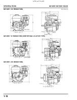
Page 16: ...1 11 GX120K1 GX160K1 GX200 SPECIFICATIONS 4 DIMENSIONAL DRAWINGS GX120K1 Unit mm in gx120k1_gx160k1_gx200 ...

Page 17: ...GX120K1 1 2 REDUCTION CENTRIFUGAL CLUTCH TYPE GX120K1 1 6 REDUCTION 3 15 3 4 1 4 3 15 76 3 0 35 7 1 4 80 3 15 1 6 39 5 5 0 2 2 9x14 SLOT 2 9 HOLE 127 15 5 006 156 6 1 330 14 6 91 3 6 201 2 7 92 66 96 2 6 3 6 106 4 2 318 12 5 312 12 3 Unit mm in gx120k1_gx160k1_gx200 ...

Page 18: ...1 13 GX120K1 GX160K1 GX200 SPECIFICATIONS GX120K1 RAMMER TYPE Unit mm in gx120k1_gx160k1_gx200 ...

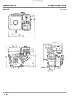
Page 19: ...1 14 SPECIFICATIONS GX120K1 GX160K1 GX200 GX160K1 Unit mm in gx120k1_gx160k1_gx200 ...

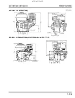
Page 20: ...1 15 GX120K1 GX160K1 GX200 SPECIFICATIONS GX160K1 1 2 REDUCTION GX160K1 1 2 REDUCTION CENTRIFUGAL CLUTCH TYPE Unit mm in gx120k1_gx160k1_gx200 ...

Page 21: ...1 16 SPECIFICATIONS GX120K1 GX160K1 GX200 GX160K1 1 6 REDUCTION GX160K1 RAMMER TYPE Unit mm in gx120k1_gx160k1_gx200 ...

Page 22: ...1 17 GX120K1 GX160K1 GX200 SPECIFICATIONS GX200 CRANKSHAFT P T O S Q U P T and V TYPES Unit mm in gx120k1_gx160k1_gx200 ...

Page 23: ...1 18 SPECIFICATIONS GX120K1 GX160K1 GX200 GX200 CAMSHAFT P T O 1 2 REDUCTION N TYPE GX200 1 2 REDUCTION L TYPE Unit mm in gx120k1_gx160k1_gx200 ...

Page 24: ...1 19 GX120K1 GX160K1 GX200 SPECIFICATIONS GX200 1 2 REDUCTION WITH CENTRIFUGAL CLUTCH R TYPE GX200 1 6 REDUCTION H TYPE Unit mm in gx120k1_gx160k1_gx200 ...

Page 25: ...T P T O Unit mm in 61 7 2 43 58 5 2 30 17 0 7 5 16 24UNF 2B 4 73 4 78 0 186 0 188 16 26 16 36 0 640 0 644 61 7 2 43 58 5 2 30 Unit mm in Q type P type 3 4 16UNF 2ARH 22 5 0 89 19 025 19 050 0 7490 0 4500 GX120 78 3 1 GX160 GX200 74 2 9 GX120 78 3 1 GX160 GX200 74 2 9 GX120 19 000 19 050 0 7480 0 7500 GX160 GX200 19 025 19 050 0 7490 0 7500 gx120k1_gx160k1_gx200 ...

Page 26: ... 9 18 927 19 177 0 7452 0 7550 71 7 2 82 Unit mm in U type V type Unit mm in 5 16 24UNF 2B TAPER 2 1 4 33 5 1 32 19 830 19 843 0 7807 0 7812 14 225 14 275 0 5600 0 5620 19 000 19 050 0 7480 0 7500 8 0 3 66 2 6 56 2 2 1 2 20UNF 2ARH 3 954 3 984 0 1557 0 1569 9 90 10 00 0 390 0 394 GX120 78 3 1 GX160 GX200 74 2 9 GX120 78 3 1 GX160 GX200 74 2 9 Unit mm in W type GX120 M14 x 1 5 GX160 M18 x 1 5 GX120...

Page 27: ...880 REDUCTION UNIT P T O SHAFT 45 1 1 78 Unit mm in L type REDUCTION UNIT P T O SHAFT M8 x 1 25 53 2 2 09 50 2 0 23 0 9 5 00 5 03 0 197 0 198 54 2 1 41 25 1 624 66 1 2 60 45 45 M8 x 1 25 6 PLACES GX120 17 957 17 984 0 7070 0 7080 GX160 GX200 19 947 19 980 0 7853 0 7866 GX120 14 90 15 00 0 587 0 591 GX160 GX200 16 90 17 00 0 665 0 669 93 5 3 68 65 1 2 56 gx120k1_gx160k1_gx200 ...

Page 28: ...ammer type Unit mm in R type REDUCTION UNIT 89 7 3 53 45 45 M8 x 1 25 4 PLACES P T O SHAFT M8 x 1 25 7 000 7 036 0 2756 0 2770 17 90 18 00 0 705 0 709 52 7 2 07 50 2 0 25 1 0 50 2 0 21 947 21 980 0 8641 0 8654 70 2 8 70 2 8 gx120k1_gx160k1_gx200 ...

Page 29: ...PECIFICATIONS GX120K1 GX160K1 GX200 6 WIRING DIAGRAMS WITHOUT ELECTRIC STARTER AND OIL ALERT WITHOUT ELECTRIC STARTER WITH OIL ALERT GX120K1 2000001 2187466 GX160K1 2000001 2468253 GX200 gx120k1_gx160k1_gx200 ...

Page 30: ...0K1 2000001 2468253 GX200 WITH ELECTRIC STARTER AND OIL ALERT GX120K1 2000001 2187466 GX160K1 2000001 2468253 GX200 Bl BLACK Br BROWN COMBINATION SWITCH CONTINUITY Y YELLOW O ORANGE Bu BLUE Lb LIGHT BLUE COLOR Bl R Bl W Bl W G GREEN Lg LIGHT GREEN OFF R RED P PINK ON W WHITE Gr GRAY START gx120k1_gx160k1_gx200 ...

Page 31: ... GX160K1 GX200 WITHOUT ELECTRIC START WITH OIL ALERT GX120K1 2187467 subsequent GX160K1 2468254 subsequent GX200 WITH ELECTRIC START WITH OIL ALERT GX120K1 2187467 subsequent GX160K1 2468254 subsequent GX200 gx120k1_gx160k1_gx200 ...

Page 32: ... WITH OIL ALERT Charging System A 0 75 mm2 diameter wire 18 gauge AWG wire or larger diameter gauge wire must be used between the battery and sub wire harness This same size wire must also be used between the regulator rectifier and the frame ground Ignition System gx120k1_gx160k1_gx200 ...

Page 33: ...2 1 2 SERVICE INFORMATION 1 SERIAL NUMBER LOCATION 2 2 2 MAINTENANCE STANDARDS 2 3 3 TORQUE VALUES 2 9 4 TOOLS 2 10 5 TROUBLESHOOTING 2 12 gx120k1_gx160k1_gx200 ...

Page 34: ...ATION GX120K1 GX160K1 GX200 1 SERIAL NUMBER LOCATION The engine serial number the type and the variation are stamped on the crankcase Refer to these when ordering parts or making technical inquiries gx120k1_gx160k1_gx200 ...

Page 35: ...s Ring side clearance Top 0 015 0 045 mm 0 0006 0 0018 in 0 035 0 070mm 0 0014 0 0028 in 4 0 15 mm 0 006 in Second 0 015 0 045 mm 0 0006 0 0018 in 0 045 0 080mm 0 0018 0 0031 in 4 Ring end gap Top 0 2 0 4 mm 0 008 0 016 in 0 2 0 35 mm 0 008 0 014 in 4 1 0 mm 0 04 in Second 0 2 0 4 mm 0 008 0 016 in 0 35 0 50 mm 0 014 0 020 in 4 Oil 0 15 0 35 mm 0 006 0 014 in 0 2 0 7 mm 0 008 0 028 in 4 Ring width...

Page 36: ...in 29 5 mm 1 16 in Camshaft Cam height IN 27 7 mm 1 09 in 27 45 mm 1 081 in EX 27 75 mm 1 093 in 27 50 mm 1 083 in Camshaft O D 13 984 mm 0 5506 in 13 916 mm 0 5479 in Crankcase cover Camshaft holder I D 14 0 mm 0 55 in 14 048 mm 0 5531 in Carburetor Main jet 60 1 62 2 3 Float height 13 7 mm 0 54 in 18 7 mm 0 74 in 3 Pilot screw opening 2 turns out 1 2 3 8 turns out 2 1 1 2 turns out 3 Spark plug ...

Page 37: ...learance Top 0 015 0 045 mm 0 0006 0 0018 in 0 035 0 070mm 0 0014 0 0028 in 4 0 15 mm 0 006 in Second 0 015 0 045 mm 0 0006 0 0018 in 0 045 0 080mm 0 0018 0 0031 in 4 Ring end gap Top 0 2 0 4 mm 0 008 0 016 in 0 2 0 35 mm 0 008 0 014 in 4 1 0 mm 0 04 in Second 0 2 0 4 mm 0 008 0 016 in 0 35 0 50 mm 0 014 0 020 in 4 Oil 0 15 0 35 mm 0 006 0 014 in 0 2 0 7 mm 0 008 0 028 in 4 Ring width Top 1 5 mm 0...

Page 38: ...mm 1 20 in 29 6 mm 1 161 in Camshaft Cam height IN 27 7 mm 1 09 in 27 45 mm 1 081 in EX 27 75 mm 1 093 in 27 50 mm 1 083 in Camshaft O D 13 984 mm 0 5506 in 13 916 mm 0 5479 in Crankcase cover Camshaft holder I D 14 0 mm 0 55 in 14 048 mm 0 5531 in Carburetor Main jet 70 1 2 72 3 Float height 13 7 mm 0 54 in 18 7 mm 0 74 in 3 Pilot screw opening 3 turns out 1 2 1 8 turns out 2 3 Spark plug Gap 0 7...

Page 39: ...d 0 2 0 4 mm 0 008 0 016 in 0 35 0 50 mm 0 014 0 020 in 5 Oil 0 15 0 35 mm 0 006 0 014 in 0 2 0 7 mm 0 008 0 028 in 5 Ring width Top 1 5 mm 0 06 in 0 95 0 97 mm 0 037 0 038 in 5 1 37 mm 0 054 in 0 93 mm 0 037 in 5 Second 1 5 mm 0 06 in 0 94 0 96 mm 0 037 0 038 in 5 1 37 mm 0 054 in 0 92 mm 0 036 in 5 Oil 2 5 mm 0 10 in 2 37 mm 0 093 in Connecting rod Small end I D 18 002 mm 0 7087 in 18 07 mm 0 71...

Page 40: ... 0 5479 in Crankcase cover Camshaft holder I D 14 0 mm 0 55 in 14 048 mm 0 5531 in Carburetor Main jet Float height Pilot screw opening 72 1 75 2 78 3 75 4 13 7 mm 0 54 in 3 turns 1 2 and 1 8 turns 2 3 4 Spark plug Spark plug cap Gap Resistance 0 7 0 8 mm 0 028 0 031 in 7 5 12 5 Ignition coil Resistance Primary coil 0 8 1 1 Secondary coil 5 9 7 1 k Air gap at flywheel 0 4 0 2 mm 0 016 0 008 in Sta...

Page 41: ...arm pivot bolt M8 x 1 25 24 18 Crankcase cover bolt GX120K1 GX160K1 GX200 M6 x 1 0 CT M8 x 1 25 M8 x 1 25 12 24 24 9 18 18 Oil level switch nut M10 x1 25 10 7 Fuel filter M10 x1 25 2 1 4 Muffler mounting nut M10 x1 25 24 18 Air cleaner wing nut M6 x 1 0 9 6 6 Oil drain bolt M10 x 1 25 18 13 Fuel tank bolt nut M6 x 1 0 10 7 Air cleaner mounting nut 6 mm cap nut M6 x 1 0 8 3 6 1 Sediment cup M24 x 1...

Page 42: ...E Tool and Equipment Program by calling 888 424 6857 Refer to the Tool and Equipment program catalog for a complete tool listing Tool name Tool number Application Valve seat cutter 115 32 Valve seat cutter 122 45 Valve seat cutter 111 60 Solid pilot bar 5 50 mm Solid pilot bar 5 52 mm Solid pilot bar 5 55 mm T Wrench 505 T Wrench adapter 503 1 Accessory package 246 NWYCU115 NWYCU122 NWYCU111 NWY10...

Page 43: ... D 07746 0030100 Driver for attachments 6 7 and 8 6 Attachment 25 mm I D 07746 0030200 Timing gear installation GX120K1 7 Attachment 30 mm I D 07746 0030300 Governor drive gear GX120K1 and timing gear GX160K1 GX200 installation 8 Attachment 35 mm I D 07746 0030400 Governor drive gear installation GX160K1 GX200 9 Pilot 20mm 07746 0040500 Bearing 6204 installation 10 Pilot 22 mm 07746 0041000 Cranks...

Page 44: ... recoil starter P 5 1 and check whether the engine cranks Cannot be cranked Perform the STARTER MOTOR DOES NOT OPERATE TROUBLESHOOTING P 2 16 Disassemble the engine and replace the faulty part s P 10 2 Cranks Inspect the recoil starter P 5 3 Abnormal Replace the faulty part s gx120k1_gx160k1_gx200 ...

Page 45: ...ow Check the valve clearance P 3 8 and then perform the cylinder compression test If the cylinder compression is too low perform a leak down test If there is no air leakage in the engine check the following Valve spring free length P 9 4 Valve seat width P 9 4 Valve face irregularly worn Piston ring side clearance P 10 7 Piston ring width P 10 7 Piston ring end gap P 10 8 Piston skirt O D P 10 7 C...

Page 46: ...clearance P 3 8 Normal Check the carburetor for any blockage P 6 4 Clogged Disassemble and clean the carburetor P 6 8 Clean Check for a secondary air leak Air leaking Check around the air intake joint and carburetor Replace the insulator and or gasket if necessary No air leaking Check the cylinder compression P 2 19 Compression too high Check for carbon deposits in the combustion chamber P 9 4 Nor...

Page 47: ...ty Replace the ignition coil wire P 8 2 Normal Check the ignition coil primary side P 8 4 Abnormal Replace the ignition coil if abnormalities are found and recheck P 8 2 Check the oil level switch P 11 3 Abnormal Replace the oil level switch P 11 2 Normal Check the Oil Alert unit if equipped P 5 8 Abnormal Replace the Oil Alert unit P 5 7 Normal Check the wire harness connecting the oil level swit...

Page 48: ...ESHOOTING P 2 17 Normal Check the fuse Abnormal Replace the fuse Normal Check the combination switch P 5 8 Abnormal Replace the combination switch P 5 7 Normal Check the starter solenoid P 8 5 Abnormal Replace the starter solenoid P 8 3 Normal Check the wire harness for shorts or open circuits Abnormal Replace the wiring harness Normal Disassemble the starter motor and check each part P 8 3 gx120k...

Page 49: ...rmal Check the charge lamp coil P 8 5 Abnormal Replace the charge lamp coil P 8 2 Normal Check the following Circuit protector P 5 9 Silicon rectifier P 5 9 Regulator rectifier P 5 10 Abnormal Replace the faulty part s P 5 7 Circuit protector Silicon rectifier Regulator rectifier Normal Check the harness connecting the charge coil for an open or short circuit and for proper connection If necessary...

Page 50: ... Oil Alert unit P 5 7 Without control box With control box Normal Check for continuity between the ignition coil wire connectors P 8 4 Abnormal Replace the ignition coil wire Normal Check the engine stop switch if equipped P 5 8 combination switch if equipped P 5 8 Abnormal Replace the engine stop switch combination switch P 5 7 Normal Check the ignition coil P 8 4 Abnormal Replace the ignition co...

Page 51: ...l the spark plug to the spark plug cap and ground the side electrode against the cylinder head cover 3 Turn the engine switch to the ON position pull the recoil starter and check to see if sparks jump across the electrodes Compression 6 8 5 kg cm2 85 121 psi at 600 min 1 rpm WARNING Never hold the spark plug lead with wet hands while performing this test Make sure that no fuel has been spilled on ...

Page 52: ... ENGINE OIL 3 4 3 REDUCTION CASE OIL 3 5 4 OIL ALERT 3 6 5 AIR CLEANER 3 6 6 VALVE CLEARANCE 3 8 7 SPARK PLUG 3 9 8 CARBURETOR 3 10 9 GOVERNOR 3 10 10 SEDIMENT CUP 3 11 11 SPARK ARRESTER OPTIONAL PARTS 3 11 12 FUEL FILTER 3 12 gx120k1_gx160k1_gx200 ...

Page 53: ...First month or 20 Hrs Every 3 months or 50 Hrs Every 6 months or 100 Hrs Every year or 300 Hrs Refer to page ITEM Engine oil Check level 3 3 Change Reduction gear oil Check level 3 5 Change Air cleaner Check 3 6 Clean 1 Sediment cup Clean 3 11 Spark plug Clean Readjust 3 9 Valve clearance Check Readjust 3 8 Combustion chamber and valves Clean Lap 9 3 9 4 Fuel tube Check Replace if necessary Every ...

Page 54: ... use First month or 20 Hrs Every 3 months or 50 Hrs Every 6 months or 100 Hrs Every year or 300 Hrs Refer to page Engine oil Check level 3 3 Change Reduction gear oil Check level 3 5 Change Air filter Check 3 6 Clean 1 1 Cyclone type Every 6 months or 150 hours Replace Cyclone type Every 2 years or 600 hours Sediment cup Clean 3 11 Spark plug Check adjust 3 9 Replace Spark arrestor Optional parts ...

Page 55: ...tion SG SF CC CD Motor oils classified SG SF CC CD will show this designation on the container GX120K1 GC01 3993726 and subsequent use SJ or higher SAE 10W 30 is recommended for general all temperature use Other viscosities shown in the chart may be used when the average temperature in your area is within the indicated range Engine oil capacity GX120K1 GX160K1 GX200 0 56 L 19 oz 0 4 L 13 5 oz 1 0 ...

Page 56: ... dipstick 1 6 REDUCTION 1 Remove the filler bolt and oil level bolt Tilt the engine to drain the used oil through the oil level bolt hole Allow the oil to drain completely 2 Stand the engine upright and fill the reduction case with the same oil that is recommended for the engine Fill until oil starts to flow from the oil level bolt hole 3 Install the oil level bolt and filler bolt Tighten them to ...

Page 57: ... elements and separate them Carefully check both elements for holes or tears and replace if damaged 2 Foam element Clean in warm soapy water rinse and allow to dry thoroughly or clean in high flash point solvent and allow to dry Dip the element in clean engine oil and squeeze out all the excess The engine will smoke during initial startup if too much oil is left in the foam 3 Paper element Tap the...

Page 58: ...stem may need daily maintenance Semi dry type 1 Remove the wing nut air cleaner cover and foam element Carefully check the element for holes or tears and replace if damaged 2 Clean wash and oil the foam element P 3 6 Oil bath type 1 Remove the wing nut air cleaner cover and foam element Carefully check the element for holes or tears and replace if damaged 2 Clean wash and oil the foam element P 3 ...

Page 59: ...ring initial start up if too much oil is left in the foam 4 Insert the open end of the filter assembly into the air cleaner case so the closed end is at the cover 6 VALVE CLEARANCE Note Valve clearance inspection and adjustment must be performed when the engine is cold 1 Remove the four cylinder head cover bolts cylinder head cover and gasket 2 Set the piston at top dead center of the compression ...

Page 60: ...ator is cracked or chipped 2 Measure the plug gap with a wire type feeler gauge If necessary adjust the gap by bending the side electrode 3 Make sure the sealing washer is in good condition replace the plug if necessary 4 Install the plug finger tight to seat the washer then tighten with a plug wrench an additional 1 2 turn if a new plug to compress the sealing washer If you are reusing a plug tig...

Page 61: ... the pilot screw is correctly adjusted turn the throttle stop screw to obtain the standard idle speed 1 Rammer type 9 GOVERNOR 1 Remove the fuel tank P 7 1 2 Loosen the nut on the governor arm and move the governor arm to fully open the throttle 3 Rotate the governor arm shaft as far as it will go in the same direction the governor arm moved to open the throttle Tighten the nut on the governor arm...

Page 62: ...d the exhaust port and spark arrester Clean if necessary Replace the spark arrester if there are any breaks or tears 5 Install the spark arrester and upper muffler protector in the reverse order of removal WARNING Gasoline is extremely flammable and is explosive under certain conditions Do not smoke or allow flames or sparks in the area After installing the fuel filter check for leaks and make sur...

Page 63: ...sure the filter screen is undamaged 4 Place the O ring on the filter and reinstall Tighten the filter to the specified torque After reassembly check for fuel leaks TORQUE 2 N m 1 4 ft lb WARNING Gasoline is extremely flammable and is explosive under certain conditions Do not smoke or allow flames or sparks in the area After installing the fuel filter check for leaks and make sure the area is dry b...

Page 64: ...EANER 4 1 2 MUFFLER 4 5 BREATHER TUBE REASSEMBLY After installing on the air cleaner elbow insert into the hole in the cylinder head cover CALIFORNIA MODELS Slide the breather tube over the cylinder head cover nipple and secure both ends with the hose clips P 3 6 P 3 6 gx120k1_gx160k1_gx200 ...

Page 65: ...4 2 AIR CLEANER MUFFLER GX120K1 GX160K1 GX200 SEMI DRY TYPE AAAAAAAAAAAAAAAAAAAAAAAADUAL ELEMENT TYPE P 3 6 P 3 6 P 3 6 gx120k1_gx160k1_gx200 ...

Page 66: ...4 3 GX120K1 GX160K1 GX200 AIR CLEANER MUFFLER OIL BATH TYPE AAAAAAAAAAAAAAAAAAAAAAACYCLONE TYPE P 3 6 P 3 6 P 3 6 gx120k1_gx160k1_gx200 ...

Page 67: ...4 4 AIR CLEANER MUFFLER GX120K1 GX160K1 GX200 Rammer type P 3 6 P 3 6 gx120k1_gx160k1_gx200 ...

Page 68: ...4 5 GX120K1 GX160K1 GX200 AIR CLEANER MUFFLER 2 MUFFLER DISASSEMBLY REASSEMBLY P 3 11 gx120k1_gx160k1_gx200 ...

Page 69: ...4 6 AIR CLEANER MUFFLER GX120K1 GX160K1 GX200 Rammer type gx120k1_gx160k1_gx200 ...

Page 70: ... DISASSEMBLY REASSEMBLY GX120K1 GX160K1 1 RECOIL STARTER 5 1 2 FAN COVER 5 6 3 CONTROL BOX STARTER MOTOR EQUIPPED TYPE 5 7 WARNING Wear gloves and eye protection During assembly take care not to allow return spring to come out gx120k1_gx160k1_gx200 ...

Page 71: ...5 2 RECOIL STARTER FAN COVER GX120K1 GX160K1 GX200 GX200 gx120k1_gx160k1_gx200 ...

Page 72: ...R DISASSEMBLY REASSEMBLY CONTINUED RECOIL STARTER ASSEMBLY 1 Insert the hook on the outer side of the spring into the groove inside the reel WARNING Wear gloves and eye protection During assembly take care not to allow return spring to come out gx120k1_gx160k1_gx200 ...

Page 73: ...ter reel 3 Install the starter reel on the starter case so that the spring inner hook is hooked to the case tab 4 Hold the starter case and rotate the starter reel two revolutions in the direction of the arrow for preliminary winding 5 Pass the starter rope end through the starter case rope guide and pull it outwards Pass the starter rope through the starter grip and tie the rope as shown WARNING ...

Page 74: ...60K1 GX200 RECOIL STARTER FAN COVER 6 Install the ratchet with the spring and reel cover Tighten the reel cover bolt 7 Check the operation of the ratchet by pulling the starter rope several times gx120k1_gx160k1_gx200 ...

Page 75: ...5 6 RECOIL STARTER FAN COVER GX120K1 GX160K1 GX200 2 FAN COVER DISASSEMBLY REASSEMBLY P 5 8 P 5 7 P 5 8 P 5 8 gx120k1_gx160k1_gx200 ...

Page 76: ...5 7 GX120K1 GX160K1 GX200 RECOIL STARTER FAN COVER 3 CONTROL BOX STARTER MOTOR EQUIPPED TYPE DISASSEMBLY REASSEMBLY P 5 9 P 5 8 P 5 8 P 5 9 gx120k1_gx160k1_gx200 ...

Page 77: ...shown The Oil Alert lamp should light Replace the Oil Alert unit if the lamp does not light Black lead to battery Yellow lead to battery CONTROL BOX STARTER MOTOR EQUIPPED TYPE 1 COMBINATION SWITCH Check for continuity between the wires shown in the following table There should be continuity between 0 0 marks with the switch in the indicated position Replace the combination switch if the correct c...

Page 78: ...ity between the terminals There should be continuity in one direction only Replace the rectifier if there is continuity in both directions or in neither direction 4 CIRCUIT BREAKER Check continuity between the two terminals There should be continuity in the ON position button in and no continuity in the OFF position button out Replace the circuit breaker if the correct continuity is not obtained C...

Page 79: ... K Note Use the diode check function of a digital multimeter or the R x 1 scale of an ordinary analog meter Some meters show current flow from negative to positive and others show flow from positive to negative The polarity of the meter does not matter when testing diodes As long as the meter shows current flowing one way and not the other the diode is good Gr1 Gr2 W Bl Gr1 Gr2 W 1 200 1 200 0 5 1...

Page 80: ...6 1 6 CARBURETOR 1 CARBURETOR 6 2 gx120k1_gx160k1_gx200 ...

Page 81: ...6 2 CARBURETOR GX120K1 GX160K1 GX200 1 CARBURETOR REMOVAL INSTALLATION gx120k1_gx160k1_gx200 ...

Page 82: ...6 3 GX120K1 GX160K1 GX200 CARBURETOR Rammer type gx120k1_gx160k1_gx200 ...

Page 83: ...REASSEMBLY NOTICE Tampering is violation of Federal and California Law WARNING Remove the drain bolt and drain the carburetor before disassembling Fuel vapor or spilled fuel may ignite P 3 10 P 6 8 P 3 10 P 3 11 P 2 4 P 2 6 P 2 8 gx120k1_gx160k1_gx200 ...

Page 84: ...6 5 GX120K1 GX160K1 GX200 CARBURETOR Rammer type P 3 10 P 3 1 NOTICE Tampering is violation of Federal and California Law 72 gx120k1_gx160k1_gx200 ...

Page 85: ...pering is violation of Federal and California Law DISASSEMBLY ASSEMBLY P 3 10 P 6 7 P 6 8 P 6 7 P 3 11 P 2 4 P 2 6 P 2 8 FUEL DRAIN BOLT WARNING Remove the drain bolt and drain the carburetor before disassembling Fuel vapor or spilled fuel may ignite gx120k1_gx160k1_gx200 ...

Page 86: ...ated then turn the screw out the required number of turns 4 Apply LOCTITE 638 to the inside of the limiter cap then install the cap so its stop prevents the pilot screw from being turned counterclockwise Be careful to avoid turning the pilot screw while installing the limiter cap The pilot screw must stay at its required setting PILOT SCREW REQUIRED SETIING ENGINE CARBURETOR AND AIR CLEANER COMBIN...

Page 87: ...RNAL vent ports are found on the carburetor Carburetors that are EXTERNALLY VENTED the external vent passage is open to the carburetor bowl and the internal vent passage is closed Carburetors that are INTERNALLY VENTED the internal vent passage is open to the carburetor bowl and the external vent passage is closed Standard float height 13 7 mm 0 54 in WARNING To prevent serious eye injury always w...

Page 88: ...Y 1 FUEL TANK CONTROL BASE 7 1 2 GOVERNOR ARM 7 3 3 FUEL TANK CAP U UT U1 UT1 TYPE 7 4 4 EVAPORATIVE EMISSION CONTROL SYSTEM 7 5 5 FUEL FILTER U UT U1 UT1 TYPE 7 6 WARNING Before disassembly drain the tank and fuel line completely Fuel vapor or spilled fuel may ignite gx120k1_gx160k1_gx200 ...

Page 89: ...P 3 10 FUEL TANK FUEL CAPACITY GX120K1 2 0 0 52 US gal 0 43 Imp gal GX160K1 GX200 3 1 0 81 US gal 0 68 Imp gal REASSEMBLY Wash to remove the sediment and dry thoroughly before installing FUEL FILTER 2 0 N m 0 2 kg m 1 4 ft lb CLEANING P 3 12 gx120k1_gx160k1_gx200 ...

Page 90: ...7 3 GX120K1 GX160K1 GX200 FUEL TANK GOVERNOR ARM CONTROL BASE 2 GOVERNOR ARM Adjust the governor P 3 10 gx120k1_gx160k1_gx200 ...

Page 91: ...level gauge to slacken the fuel filler cap tether INSTALLATION 1 Lower the ring of the fuel tank cap tether to the fuel filler neck 2 Set the fuel level gauge to the fuel filler neck by aligning the fuel tank cap tether hole with the cutout of the fuel filler neck and then turn the fuel level gauge 90 degrees in the reverse order of removal While installing the fuel level gauge put the fuel tank c...

Page 92: ... PRINCIPLE CHARGING Gasoline vapor produced in the fuel tank at high ambient temperature is absorbed and stored by the charcoal in the canister which is built into the fuel tank cap PURGING When the pressure in the fuel tank decreases because of low ambient temperature or consumption of gasoline the air drawn through the canister releases the stored gasoline vapor from the charcoal The released ga...

Page 93: ...R U UT U1 UT1 TYPE REMOVAL INSTALLATION Remove or install the fuel filter by aligning the cutout of the fuel filter with the fuel tank cap tether as shown The fuel tank cap and fuel level gauge can be removed or installed without removing the fuel filter gx120k1_gx160k1_gx200 ...

Page 94: ...8 1 8 FLYWHEEL IGNITION COIL STARTER MOTOR 1 FLYWHEEL IGNITION COIL 1 FLYWHEEL IGNITION COIL 8 1 2 STARTER MOTOR 8 3 gx120k1_gx160k1_gx200 ...

Page 95: ...8 2 FLYWHEEL IGNITION COIL STARTER MOTOR GX120K1 GX160K1 GX200 DISASSEMBLY REASSEMBLY page 8 3 P 8 5 P 8 5 P 8 4 gx120k1_gx160k1_gx200 ...

Page 96: ...8 3 GX120K1 GX160K1 GX200 FLYWHEEL IGNITION COIL STARTER MOTOR 2 STARTER MOTOR P 8 6 P 8 6 P 8 7 P 8 7 P 8 5 gx120k1_gx160k1_gx200 ...

Page 97: ... part of the flywheel when adjusting INSPECTION IGNITION COIL Primary side Measure the resistance of the primary coil by attaching one ohmmeter lead to the ignition coil s primary black lead while touching the other test lead to the iron core Secondary side Measure the resistance of the secondary side of the coil by removing the spark plug cap and touching one test lead to the spark plug lead wire...

Page 98: ...age 13 1 to properly identify the lamp coil before testing CHARGE COIL Measure resistance as shown STARTER SOLENOID Connect a 12 V battery between the starter terminal and the solenoid body and check for continuity between the terminals Continuity should exist when the battery is connected and not exist when the battery is disconnected Resistance 7 5 12 5 k Resistance 6V 15W 0 21 0 27 6V 25W 0 09 ...

Page 99: ...een any two segments replace the armature Continuity check commutator to shaft Check continuity between the commutator and the armature shaft Replace the armature if continuity exists between any of the commutator segments and the armature shaft Mica depth When the mica is clogged or its depth is smaller than the service limit value recut the grooves using a hacksaw blade or a small file Standard ...

Page 100: ...overrunning clutch for smooth axial movement Apply oil or replace the overrunning clutch if necessary 2 Check the reduction gear movement by holding the pinion gear and turning the reduction gear The reduction gear should turn counterclockwise freely and should not turn clockwise 3 Check the pinion gear for wear or damage and replace if necessary Note If the pinion gear is worn or damaged the flyw...

Page 101: ...9 1 9 CYLINDER HEAD VALVES 1 CYLINDER HEAD VALVES 9 2 gx120k1_gx160k1_gx200 ...

Page 102: ...9 2 CYLINDER HEAD VALVES GX120K1 GX160K1 GX200 1 CYLINDER HEAD VALVES REMOVAL INSTALLATION P 3 9 P 9 3 8 x 55 4 GX120K1 8 x 60 4 GX160K1 GX200 gx120k1_gx160k1_gx200 ...

Page 103: ...interchange with the exhaust valve VALVE HEAD DIAMETER GX120K1 INTAKE 22 mm 0 87 in EXHAUST 19 mm 0 75 in GX160K1 GX200 INTAKE 25 mm 0 98 in EXHAUST 24 mm 0 94 in INSPECTION P 9 4 P 9 4 P 9 4 P 9 6 P 9 4 INTAKE VALVE STEM SEAL GX120K1 GC01 3993726 and subsequent and GX200 engines gx120k1_gx160k1_gx200 ...

Page 104: ...ndard or over the service limit recondition the valve seat P 9 7 CYLINDER HEAD Remove carbon deposits from the combustion chamber Clear off any gasket material from the cylinder head surface Check the spark plug hole and valve areas for cracks Check the cylinder head for warpage with a straight edge and a feeler gauge Standard Service limit 30 5 mm 1 20 In 29 5 mm 1 161n Standard Service limit 0 8...

Page 105: ... guide I D to obtain the stem to guide clearance If the stem to guide clearance exceeds the service limit determine if the new guide with standard dimensions would bring the clearance within tolerance If so replace any guide as necessary and ream to fit If the stem to guide clearance exceeds the service limit with new guides replace the valves as well Note Recondition the valve seats whenever the ...

Page 106: ...take valve guide to the specified height measured from the top of the valve guide to the cylinder casting as shown 6 After installation inspect the valve guide for damage Replace the guide if damaged VALVE GUIDE REAMING Note For best results be sure the cylinder head is at room temperature before reaming valve guides 1 Coat the reamer and valve guide with cutting oil 2 Rotate the reamer clockwise ...

Page 107: ...pply a light coat of Prussian Blue or erasable felt tipped marker ink to the valve face 2 Insert the valve and snap it closed against its seat several times Be sure the valve does not rotate on the seat The transferred marking compound will show any area of the seat that is not concentric Note Follow the instructions of the valve seat cutter manufacturer 3 Using a 45 cutter remove enough material ...

Page 108: ...rfacing the seats inspect for even valve seating Apply Prussian Blue compound or erasable felt tipped marker ink to the valve faces Insert the valve and snap it closed against its seat several times Be sure the valve does not rotate on the seat The seating surface as shown by the transferred marking compound should have good contact all the way around 7 Lap the valves into their seats using a hand...

Page 109: ...10 1 10 CRANKSHAFT COVER CRANKSHAFT PISTON 1 CRANKCASE COVER CRANKSHAFT PISTON 10 2 gx120k1_gx160k1_gx200 ...

Page 110: ...CRANKCASE COVER CRANKSHAFT PISTON DISASSEMBLY REASSEMBLY P 10 5 P 10 2 P 10 6 P 10 10 P 10 4 P 10 4 P 10 11 P 10 11 OIL SEAL GX120K1 22 x 35 x 6 GX160K1 GX200 25 x 41 x 6 GX160K1 GX200 GX160K1 GX200 8 x 32 GX160K1 GX200 24 N m 24 kg m 17 ft lb gx120k1_gx160k1_gx200 ...

Page 111: ...10 3 GX120K1 GX160K1 GX200 CRANKSHAFT COVER CRANKSHAFT PISTON RAMMER TYPE 8 x 32 6 GX160K1 GX200 gx120k1_gx160k1_gx200 ...

Page 112: ... and timing gear using a hydraulic press Remove the governor drive gear in the same way REASSEMBLY TIMING GEAR Using the old gear for reference make a mark at the same position on the new gear Using a hydraulic press driver and attachment I D special tools press the new gear onto the crankshaft Driver 07749 0010000 Attachment 52 x 55 mm 07746 0010400 Pilot 22 mm GX120K1 07746 0040100 Pilot 25 mm G...

Page 113: ...e markings facing upward Be sure that the top and second rings are not interchanged Check that the rings rotate smoothly after installation Space the piston ring end gaps 120 degrees apart and do not align the gaps with the piston pin bore TOP RING Chrome Plated SECOND RING OIL CONTROL RING INSPECTION P 10 6 aaaaa1 PIECE OIL CONTROL RINGaaaaaaaa3 PIECE OIL CONTROL RINGaaaaaaaaaaaa3 PIECE OIL CONTR...

Page 114: ...linder I D at three levels in both the X axis perpendicular to crankshaft and the Y axis parallel to crankshaft Take the maximum reading to determine cylinder wear and taper Standard Service limit GX120K1 60 0 mm 2 36 in 60 165 mm 2 3687 in GX160K1 68 0 mm 2 68 in 68 165 mm 2 6837 in GX200 gx120k1_gx160k1_gx200 ...

Page 115: ... 2 7111 in GX200 Standard Service limit 0 015 0 050 mm 0 0006 0 0020 in 0 12 mm 0 005 in Standard Service limit Top 1 5 mm 0 06 in 0 95 0 97 mm 0 037 0 038 in 1 1 37 mm 0 054 in 0 93 mm 0 037 in 1 Second 1 5 mm 0 06 in 0 94 0 96 mm 0 037 0 038 in 1 1 37 mm 0 054 in 0 92 mm 0 037 in 1 Oil 2 5 mm 0 10 in 2 37 mm 2 37 in Standard Service limit Top 0 015 0 045 mm 0 0006 0 0018 in 0 035 0 070 mm 0 0014...

Page 116: ...14 in 1 1 0 mm 0 04 in Second 0 2 0 4 mm 0 008 0 016 in 0 35 0 50 mm 0 014 0 020 in 1 Oil 0 15 0 35 mm 0 006 0 014 in Standard Service limit GX120K1 13 0 mm 0 51 in 12 594 mm 0 5100 in GX160K1 18 0 mm 0 71 in 17 954 mm 0 7068 in GX200 Standard Service limit GX120K1 13 002 mm 0 5119 in 13 048 mm 0 5137 in GX160K1 18 002 mm 0 7087 in 18 048 mm 0 7105 in GX200 Standard Service limit GX120K1 0 002 0 0...

Page 117: ... mm 0 7087 in 18 07 mm 0 711 in GX200 Standard Service limit GX120K1 26 02 mm 1 024 in 26 066 mm 1 0262 in GX160K1 30 02 mm 1 182 in 30 066 mm 1 1837 in GX200 Standard Service limit GX120K1 25 770 25 783 mm 1 0146 1 0151 in 25 816 mm 1 0164 in GX160K1 29 770 29 783 mm 1 1720 1 1726 in 29 816 mm 1 1739 in GX200 Standard Service limit GX120K1 25 98 mm 1 023 25 92 mm 1 020 in GX160K1 29 98 mm 1 180 i...

Page 118: ...tate the crankshaft while the plastigauge is in place 3 Remove the connecting rod and measure the plastigauge 4 If the clearance exceeds the service limit replace the connecting rod and recheck the clearance Replacement connecting rods are available with standard and undersized bearing surfaces CAMSHAFT CAM HEIGHT Standard Service limit 0 1 0 7 mm 0 004 0 028 in 1 1 mm 0 043 in Standard Service li...

Page 119: ... Clean the bearing in solvent and dry it 2 Spin the bearing by hand and check for play Replace the bearing if it is noisy or has excessive play CAMSHAFT HOLDER I D Standard Service limit 13 984 mm 0 5506 in 13 916 mm 0 5479 in Standard Service limit 14 0 mm 0 55 in 14 048 mm 0 5531 in gx120k1_gx160k1_gx200 ...

Page 120: ...11 1 11 GOVERNOR OIL LEVEL SWITCH 1 GOVERNOR OIL LEVEL SWITCH 11 2 gx120k1_gx160k1_gx200 ...

Page 121: ...11 2 GOVERNOR OIL LEVEL SWITCH GX120K1 GX160K1 GX200 1 GOVERNOR OIL LEVEL SWITCH DISASSEMBLY REASSEMBLY P 11 3 gx120k1_gx160k1_gx200 ...

Page 122: ... with an ohmmeter 1 Hold the switch in its normal position The ohmmeter should read zero resistance 2 Hold the switch upside down The ohmmeter should read infinite resistance 3 Inspect the float by dipping the switch into a container of oil The ohmmeter reading should go from zero to infinity as the switch is lowered gx120k1_gx160k1_gx200 ...

Page 123: ...12 1 12 REDUCTION UNIT 1 L TYPE REDUCTION 12 2 2 1 2 REDUCTION CENTRIFUGAL CLUTCH TYPE 12 3 3 CAMSHAFT P T O 1 2 REDUCTION N TYPE 12 4 4 1 6 REDUCTION 12 5 5 RAMMER TYPE 12 6 gx120k1_gx160k1_gx200 ...

Page 124: ...12 2 REDUCTION UNIT GX120K1 GX160K1 GX200 1 L TYPE REDUCTION DISASSEMBLY REASSEMBLY gx120k1_gx160k1_gx200 ...

Page 125: ...12 3 GX120K1 GX160K1 GX200 REDUCTION UNIT 2 1 2 REDUCTION CENTRIFUGAL CLUTCH TYPE DISASSEMBLY REASSEMBLY P 12 7 P 12 7 gx120k1_gx160k1_gx200 ...

Page 126: ...12 4 REDUCTION UNIT GX120K1 GX160K1 GX200 3 CAMSHAFT P T O 1 2 REDUCTION N TYPE gx120k1_gx160k1_gx200 ...

Page 127: ...12 5 GX120K1 GX160K1 GX200 REDUCTION UNIT 4 1 6 REDUCTION DISASSEMBLY REASSEMBLY 07746 0010500 DRIVER gx120k1_gx160k1_gx200 ...

Page 128: ...12 6 REDUCTION UNIT GX120K1 GX160K1 GX200 5 RAMMER TYPE 6005 BALL BEARING gx120k1_gx160k1_gx200 ...

Page 129: ... UNIT INSPECTION CLUTCH FRICTION DISC THICKNESS CLUTCH PLATE WARPAGE Check clutch plate warpage on a flat plate using a feeler gauge Standard Service limit 3 5 mm 0 14 in 3 0 mm 0 12 in Service limit 0 10 mm 0 004 in gx120k1_gx160k1_gx200 ...

Page 130: ...pairs to produce the desired output FLYWHEEL 1 LAMP COIL KIT 13 1 2 REMOTE CONTROL CHOKE KIT 13 2 3 REMOTE CONTROL THROTTLE KIT 13 2 LAMP COIL TYPES ONE COIL TWO COILS SERIES TWO COILS PARALLEL 6V 15W 6V 15W 12 V 15W 6 V 30W 6V 25W 6V 25W 12 V 25W 6 V 50W 12 V 15W 12 V 15W 24 V 15W 12 V 30W 12 V 25W 12 V 25W 24 V 25W 12 V 50W gx120k1_gx160k1_gx200 ...

Page 131: ... commercially available stranded cable may be used 3 REMOTE CONTROL THROTTLE KIT 1 Installation direction May be installed in two ways either on the throttle lever side A or the cylinder head side B 2 Types of cable Two types can be used stranded wire C and solid wire E commercial products may be used In the case of stranded wire a cable end D should be used and in the case of solid wire attach di...

Page 132: ...ee play 10 11 Bearing reassembly 10 4 Disassembly reassembly 10 2 Cylinder compression GX120 2 3 GX160 2 5 GX200 2 7 Cylinder head Carbon deposit removal 9 4 Cylinder I D inspection 10 6 Disassembly reassembly 9 3 Inspection 9 4 Removal installation 9 2 Warpage 9 4 D Diagrams wiring 1 24 Dimensional drawings GX120 1 11 GX160 1 14 GX200 1 17 Dimensions and weights GX120 1 5 GX160 1 6 GX200 1 7 E Em...

Page 133: ...assembly 10 5 Side clearance 10 7 Width 10 7 Rod connecting Big end I D 10 9 Big end oil clearance 10 10 Big end side clearance 10 10 Small end I D 10 9 Rules service ii iii S Safety messages ii Schedule maintenance 3 2 Sediment cup cleaning 3 11 Serial number location 2 2 Service rules ii iii Solenoid starter 8 5 Spark arrester cleaning 3 11 Spark plug 3 9 Spark plug cap inspection 8 5 Spark test...

Reviews: