GOVERNOR SYSTEM
7-7
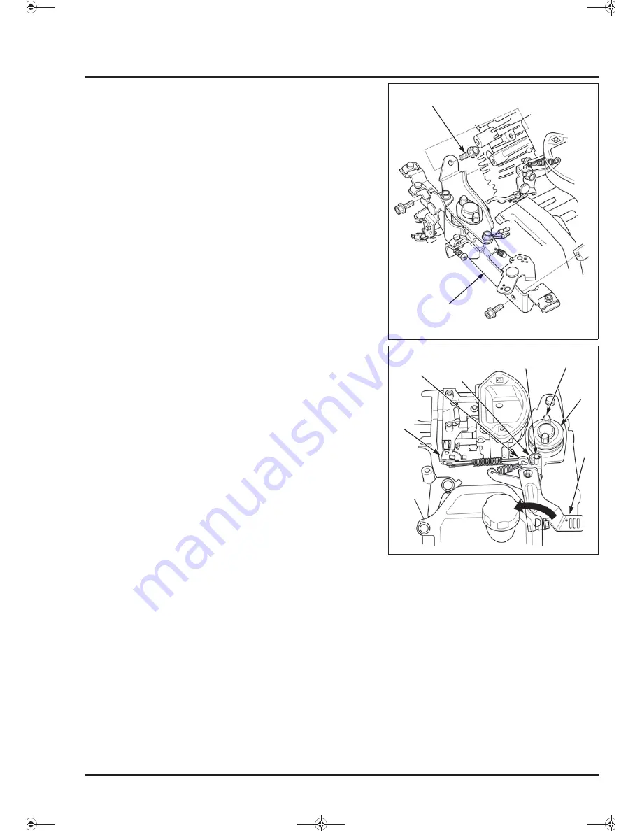
Route the auto throttle solenoid harness on the upper
shroud loosely (page 2-9).
Install the control (1) on the cylinders and tighten the
three bolts (2).
Hook the governor spring and start spring to the
governor arm (page 7-4).
Rotate the governor arm (1) to fully open the throttle
valve (2).
Slowly rotate the auto throttle solenoid (3) so the
distance between the auto throttle lever (4) and the pin
(5) of the governor sub arm (6) is in the specified
clearance.
Do not rotate the governor sub arm during this
procedure.
Tighten the special cap nuts (7) to secure the auto
throttle solenoid.
Check the clearance between the auto throttle lever
and the governor sub arm pin.
Take up the slack of the auto throttle solenoid harness
and route the crankcase (page 2-9).
Rotate the governor arm to fully open the throttle valve
and be sure that the pin on the governor sub arm is not
touching to the auto throttle lever.
(1)
(2)
CLEARANCE: 0 – 1 mm (0 – 0.04 in)
(3)
(7)
(1)
(2)
(4)
(5)
(6)
<0DQQMࡍࠫ㧞㧜㧜㧥ᐕ㧢㧝㧢ᣣޓἫᦐᣣޓඦᓟ㧢ᤨ㧝㧣ಽ
Summary of Contents for GX630
Page 1: ...HONDA GX690 WORKSHOP MANUAL ...
Page 18: ...MEMO 0 DQQM ࡍ ࠫ 㧞㧜㧜㧥ᐕ㧢 㧝㧢ᣣ ޓ Ἣᦐᣣ ޓ ඦᓟ㧢ᤨ㧝㧣ಽ ...
Page 44: ...MEMO 0 DQQM ࡍ ࠫ 㧞㧜㧜㧥ᐕ㧢 㧝㧢ᣣ ޓ Ἣᦐᣣ ޓ ඦᓟ㧢ᤨ㧝㧣ಽ ...
Page 54: ...MEMO 0 DQQM ࡍ ࠫ 㧞㧜㧜㧥ᐕ㧢 㧝㧢ᣣ ޓ Ἣᦐᣣ ޓ ඦᓟ㧢ᤨ㧝㧣ಽ ...
Page 86: ...MEMO 0 DQQM ࡍ ࠫ 㧞㧜㧜㧥ᐕ㧢 㧝㧢ᣣ ޓ Ἣᦐᣣ ޓ ඦᓟ㧢ᤨ㧝㧣ಽ ...
Page 100: ...MEMO 0 DQQM ࡍ ࠫ 㧞㧜㧜㧥ᐕ㧢 㧝㧢ᣣ ޓ Ἣᦐᣣ ޓ ඦᓟ㧢ᤨ㧝㧣ಽ ...
Page 106: ...MEMO 0 DQQM ࡍ ࠫ 㧞㧜㧜㧥ᐕ㧢 㧝㧢ᣣ ޓ Ἣᦐᣣ ޓ ඦᓟ㧢ᤨ㧝㧣ಽ ...
Page 140: ...MEMO 0 DQQM ࡍ ࠫ 㧞㧜㧜㧥ᐕ㧢 㧝㧢ᣣ ޓ Ἣᦐᣣ ޓ ඦᓟ㧢ᤨ㧝㧣ಽ ...


