OTHER ELECTRICAL
11-4
COMBINATION SWITCH INSPECTION
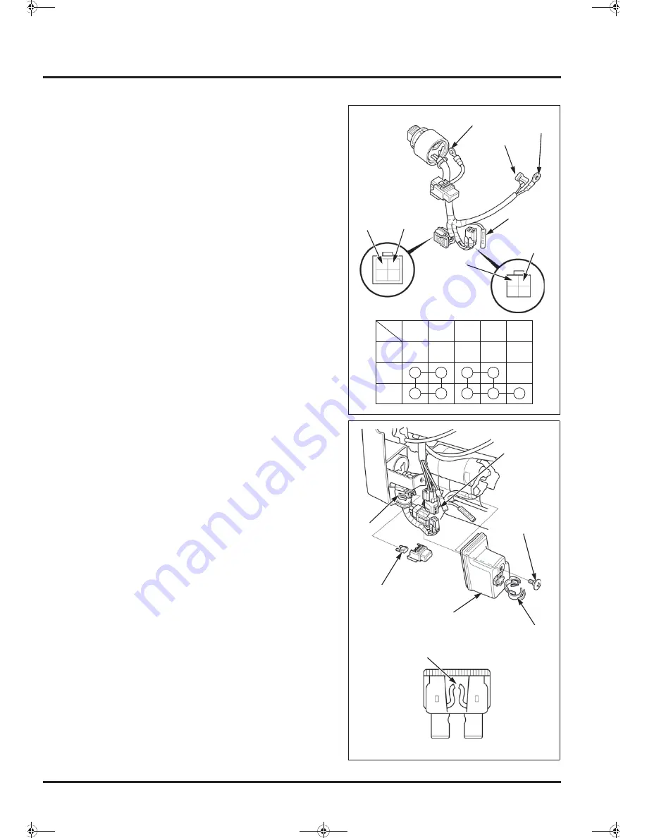
Remove the combination switch (page 7-10).
Check continuity between the terminals at each switch
position.
If the correct continuity is not obtained, replace the
combination switch (page 7-10).
Disconnect the charge coil connectors and combination
switch 4P connector (1). Remove the combination
switch 4P connector, and open the wire harness clip (2)
to remove the wire harness.
Remove the special screw (3) and the control cover (4).
Remove the blade fuse (5) from the fuse box (6).
Visually inspect the blade fuse.
Check continuity between the blades of the fuse.
If there is not continuity, replace the blade fuse.
OFF
ON
IGN GND
ST
BAT
LO
ST
ST
IGN
(Bl)
BAT
BAT
LO
(Bl/Y)
GND
(G)
GND
LO
(Bl/Y)
(1)
(2)
(4)
(5)
(6)
(3)
Blown
<0DQQMࡍࠫ㧞㧜㧜㧥ᐕ㧢㧝㧢ᣣޓἫᦐᣣޓඦᓟ㧢ᤨ㧝㧣ಽ
Summary of Contents for GX630
Page 1: ...HONDA GX690 WORKSHOP MANUAL ...
Page 18: ...MEMO 0 DQQM ࡍ ࠫ 㧞㧜㧜㧥ᐕ㧢 㧝㧢ᣣ ޓ Ἣᦐᣣ ޓ ඦᓟ㧢ᤨ㧝㧣ಽ ...
Page 44: ...MEMO 0 DQQM ࡍ ࠫ 㧞㧜㧜㧥ᐕ㧢 㧝㧢ᣣ ޓ Ἣᦐᣣ ޓ ඦᓟ㧢ᤨ㧝㧣ಽ ...
Page 54: ...MEMO 0 DQQM ࡍ ࠫ 㧞㧜㧜㧥ᐕ㧢 㧝㧢ᣣ ޓ Ἣᦐᣣ ޓ ඦᓟ㧢ᤨ㧝㧣ಽ ...
Page 86: ...MEMO 0 DQQM ࡍ ࠫ 㧞㧜㧜㧥ᐕ㧢 㧝㧢ᣣ ޓ Ἣᦐᣣ ޓ ඦᓟ㧢ᤨ㧝㧣ಽ ...
Page 100: ...MEMO 0 DQQM ࡍ ࠫ 㧞㧜㧜㧥ᐕ㧢 㧝㧢ᣣ ޓ Ἣᦐᣣ ޓ ඦᓟ㧢ᤨ㧝㧣ಽ ...
Page 106: ...MEMO 0 DQQM ࡍ ࠫ 㧞㧜㧜㧥ᐕ㧢 㧝㧢ᣣ ޓ Ἣᦐᣣ ޓ ඦᓟ㧢ᤨ㧝㧣ಽ ...
Page 140: ...MEMO 0 DQQM ࡍ ࠫ 㧞㧜㧜㧥ᐕ㧢 㧝㧢ᣣ ޓ Ἣᦐᣣ ޓ ඦᓟ㧢ᤨ㧝㧣ಽ ...


