background image

2.

GENERAL REGULATIONS

2.1

Precautions while working

Work carried out on the lawn-tractor is not as a rule any
more dangerous than any other normal mechanical work
and accidents are preventable with the normal care and
attention taken for this type of work.

Other than the usual safety regulations connected with
typical workshop conditions, we recommend:

-

taking out the ignition key before beginning any repair
work,

-

protecting hands with suitable work gloves, especially
when working on the blades or handling the parts in
steel plate,

-

ensuring that other persons cannot accidentally carry
out actions that may physically endanger whoever is
working on the lawn-tractor.

2.2

Slings

The lawn-tractor must never be lifted using a hoist or
other lifting equipment which uses ropes.

2.3

Lifting

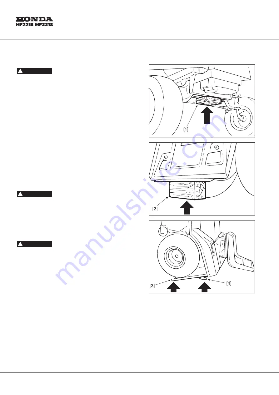
The Lawn-Tractor can be lifted by the front section using
a jack placed under the lower section of the chassis and
with a wooden block [1] between the jack and the
chassis, taking care to prevent the front beam from
swinging freely. The rear section is lifted by placing a
suitable block [2] under the lower section of the plate.

In any case, an appropriately sized wedge should be
placed behind the opposite wheels to stop the
lawn-tractor from accidentally moving backwards.

!

WARNING :

!

WARNING :

!

WARNING :

36

Summary of Contents for HF2213

Page 1: ...HF2213 HF2218 MANUEL D ATELIER WERKSTATT HANDBUCH MANUALE DI RIPARAZIONI SHOP MANUAL ...

Page 2: ...onveyor 72 5 4 Removal of rear plate 74 5 5 Removal of fuel tank and dashboard 76 5 6 Removal of the engine 78 5 7 Removal of the cutting deck 80 5 8 Removal of the pump Hydrostatic drive models 82 6 REPAIRS _____________________ 84 6 1 Replacement of tyres and wheels 84 6 2 Replacement of front wheel bearings 88 6 3 Dismantling steering pinion and ring gear 90 6 4 Replacement of drive belt 92 6 5...

Page 3: ... du réservoir et du tableau de bord 77 5 6 Démontage du moteur 79 5 7 Démontage du plateau de coupe 81 5 8 Démontage de la pompe Modèles à transmission hydrostatique 83 6 RÉPARATIONS _______________ 85 6 1 Changement des pneus et des roues 85 6 2 Changement des roulements des roues avant 89 6 3 Démontage du pignon et de la couronne du volant 91 6 4 Changement de la courroie de traction 93 6 5 Chan...

Page 4: ... 73 5 4 Ausbau der hinteren Platte 75 5 5 Ausbau des Tanks und des Armaturenbretts 77 5 6 Ausbau des Motors 79 5 7 Ausbau des Mähwerks 81 5 8 Ausbau der Pumpe Modelle mit hydrostatischem Antrieb 83 6 REPARATUREINGRIFFE _______ 85 6 1 Reifen undradwecksel 85 6 2 Auswechseln der Kudellager der vorderen Räder 89 6 3 Ausbau des Kegelrads und des Kranzes der Lenkung 91 6 4 Auswechseln der Trieberiem 93...

Page 5: ... 73 5 4 Rimozione piastra posteriore 75 5 5 Rimozione serbatoio e cruscotto 77 5 6 Rimozione del motore 79 5 7 Rimozione del piatto di taglio 81 5 8 Rimozione della pompa Modelli a trasmissione idrostatica 83 6 INTERVENTI DI RIPARAZIONE 85 6 1 Sostituzione pneumatici e ruote 85 6 2 Sostituzione cuscinetti ruote anteriori 89 6 3 Smontaggio pignone e corona dello sterzo 91 6 4 Sostituzione della cin...

Page 6: ...390 DCA GXV610 QAF4 Type 4 Stroke overhead valve single cylinder 4 Stroke overhead valve 90 V Twin Displacement cm3 389 23 7 cu in 614 37 7 cu in Bore and stroke mm 88 x 64 3 46 x 2 52 in 77 x 66 3 0 x 2 6 in Max horsepower kW 9 7 13HP 3 600 rpm 13 4 18HP 3 600 rpm Max torque N m 27 5 2 8 kg m 20 3 ft Ib 2 500 rpm 43 1 4 39 kg m 31 7 ft Ib 2 500 rpm Compression ratio 7 7 1 8 3 1 Fuel consumption g...

Page 7: ...XV610 QAF4 Type 4 temps soupape en tête mono cylindre 4 temps soupape en tête 2 cylindres en V 90 Cylindrée cm3 389 23 7 cu in 614 37 7 cu in Alésage et course mm 88 x 64 3 46 x 2 52 in 77 x 66 3 0 x 2 6 in Puissance maxi kW 9 7 13HP 3 600 min 1 tr mn 13 4 18HP 3 600 min 1 tr mn Couple maxi N m 27 5 2 8 kg m 20 3 ft Ib 2 500 min 1 tr mn 43 1 4 39 kg m 31 7 ft Ib 2500 min 1 tr mn Taux de compressio...

Page 8: ...ell GXV390 DAC GXV610 QAF4 Bauart Einzylinder 4 Takt Motor mit obengesteuerten Ventilen Obergesteuerter Viertakt Zweizylindermotor um 90 versetzt Hubraum cm3 389 23 7 cu in 614 37 7 cu in Bohrung und Hub mm 88 x 64 3 46 x 2 52 in 77 x 66 3 0 x 2 6 in Max Leistung bei 9 7 3 600 U min 13 4 3 600 U min Max Drehmoment N m 27 5 2 8 kg m 20 3 ft lb 2 500 U min 43 1 4 39 kg m 31 7 ft lb 2 500 U min Verdi...

Page 9: ...o Motore 4 tempi con valvula in testa monocilindrico Motore 4 tempi con valvula in testa 90 V Twin Cilindrata cm3 389 23 7 cu in 614 37 7 cu in Alesaggio e corsa mm 88 x 64 3 46 x 2 52 in 77 x 66 3 0 x 2 6 in Potenza massima kW 9 7 13HP 3 600 min 1 tr mn 13 4 18HP 3 600 min 1 tr mn Coppia massima N m 27 5 2 8 kg m 20 3 ft Ib 2 500 min 1 tr mn 43 1 4 39 kg m 20 3 ft lb 2 500 min 1 tr mn Rapporto di...

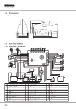
Page 10: ... BL Blue 3 Engine 8 Blades micro switch BR Brown 3a Loading coils 9 Brake micro switch GY Grey 3b Starter 10 Seat micro switch OR Orange 3c Engine stop 11 Grasscatcher micro switch RE Red 3d Oil pressure 12 Gear box micro switch VI Purple 3e Starter relay 13 Tank YG Yellow green 4 Battery 14 Regulator rectifier WH White 5 Electrolock 15 Fuse 15 Amp 10 ...

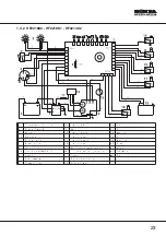
Page 11: ...tch BR Brown 3a Generator 10 Brake micro switch GY Grey 3b Loading coils 11 Seat micro switch OR Orange 3c Engine stop 12 Grasscatcher micro switch RE Red 3d Oil 13 Gear box micro switch VI Purple 3e Carburator HF2218 only 14 Full grass bag indicator YG Yellow green 4 Battery 15 Tank WH White 5 Starter relay 16 Regulator rectifier 6 Electrolock 17 Fuse 15 Amp 11 ...

Page 12: ...e Starter relay 16 Regulator rectifier YG Yellow green 4 Battery 17 Fuse 15 Amp WH White 6 Electrolock 18 Hourmeter YL Yellow 7 Headlight switch 19 Relay 8 Headlight 20 Interface H only NC 3 NO 2 C NC 3 NO 2 C NC 3 NO 2 C NC 3 NO 2 C S M G B S BL WH BR BK BR OR VI BR YG BL GY BK BR YG WH BK RE BK RE VI BK BR WH BL BR BL BL BR RE BL 6 3 AMP T a b c d 1 4 3 7 8 9 10 11 12 15 2 AVV Bt Mot AVV GND 6 1...

Page 13: ...ter relay 16 Regulator rectifier YG Yellow green 3f Carburetor 17 Fuse 15 Amp WH White 4 Battery 18 Hourmeter YL Yellow 6 Electrolock 19 Relay 7 Headlight switch 20 Interface H only 8 Headlight NC 3 NO 2 C S M G B S GY BK BR YG BK RE BK RE VI BK BR WH BL BR BL BL BR RE BL 6 3 AMP T a b c d 1 4 3 7 8 12 2 AVV Bt Mot AVV GND 6 1 2 3 4 5 6 7 8 9 10 11 12 13 CN 1 CN 3 CN 2 BZ BK 16 GY GY e 18 f NC 3 N...

Page 14: ...teur 8 Interrupteur des lames BR Marron 3a Bobines de charge 9 Interrupteur des freins GY Gris 3b Démarreur 10 Interrupteur du siège OR Orange 3c Arrêt moteur 11 Interrupteur de présence du bac RE Rouge 3d Pression huile 12 Indicateur point mort VI Violet 3e Relais démarreur 13 Réservoir YG Jaune vert 4 Batterie 14 Régulateur redresseur WH Blanc 5 Contacteur à clef 15 Fusible 15 Amp 14 ...

Page 15: ...on 3a Générateur 10 Interrupteur de frein GY Gris 3b Bobines de charge 11 Interrupteur de siège OR Orange 3c Arrêt moteur 12 Interrupteur de présence du bac RE Rouge 3d Huile 13 Indicateur point mort VI Violet 3e Carburateur HF2218 seulement 14 Indicateur bac plein YG Jaune vert 4 Batterie 15 Réservoir WH Blanc 5 Relais démarreur 16 Régulateur redresseur 6 Clef de contact 17 Fusible 15 Amp 15 ...

Page 16: ... Violet 3e Relais démarreur 16 Regulateur redresseur YG Jaune vert 4 Batterie 17 Fusible 15 Amp WH Blanc 6 Contacteur à clef 18 Compteur horaire YL Jaune 7 Interrupteur des phares 19 Relais 8 Phares 20 Interface H seulement NC 3 NO 2 C NC 3 NO 2 C NC 3 NO 2 C NC 3 NO 2 C S M G B S BL WH BR BK BR OR VI BR YG BL GY BK BR YG WH BK RE BK RE VI BK BR WH BL BR BL BL BR RE BL 6 3 AMP T a b c d 1 4 3 7 8 ...

Page 17: ... 3e Relais démarreur 16 Regulateur redresseur YG Jaune vert 3f Carburateur 17 Fusible 15 Amp WH Blanc 4 Batterie 18 Compteur horaire YL Jaune 6 Contacteur à clef 19 Relais 7 Interrupteur des phares 20 Interface H seulement 8 Phares NC 3 NO 2 C S M G B S GY BK BR YG BK RE BK RE VI BK BR WH BL BR BL BL BR RE BL 6 3 AMP T a b c d 1 4 3 7 8 12 2 AVV Bt Mot AVV GND 6 1 2 3 4 5 6 7 8 9 10 11 12 13 CN 1 ...

Page 18: ...BL Blau 3 Motor 8 Mikroschalter Messer BR Braun 3a Ladespulen 9 Mikroschalter Bremse GY Grau 3b Anlassermotor 10 Mikroschalter Sitz OR Orange 3c Motorschalter 11 Mikroschalter Sack RE Rot 3d Öldruck 12 Getriebe Mikroschalter VI Violett 3e Anlasserrelais 13 Tank YG Gelb grün 4 Batterie 14 Regler Gleichrichter WH Weiß 5 Zündschalter 15 Sicherung 15 Amp 18 ...

Page 19: ...Braun 3a Stromerzeugunsaggregat 10 Mikroschalter Bremse GY Grau 3b Ladespulen 11 Mikroschalter Sitz OR Orange 3c Motorschalter 12 Mikroschalter Sack RE Rot 3d Öl 13 Getriebe Mikroschalter VI Violett 3e Vergaser HF2218 nur 14 Schnittgut Füllstandanzeige YG Gelb grün 4 Batterie 15 Tank WH Weiß 5 Starterrelais 16 Regler Gleichrichter 6 Zündschlüssel 17 Sicherung 15 Amp 19 ...

Page 20: ...rrelais 16 Regler Gleichrichter YG Gelb grün 4 Batterie 17 Sicherung 15 Amp WH Weiß 6 Zündschalter 18 Betriebsstundenzähler YL Gelb 7 Mikroschalter Leuchten 19 Relay 8 Leucten 20 Interface nur H NC 3 NO 2 C NC 3 NO 2 C NC 3 NO 2 C NC 3 NO 2 C S M G B S BL WH BR BK BR OR VI BR YG BL GY BK BR YG WH BK RE BK RE VI BK BR WH BL BR BL BL BR RE BL 6 3 AMP T a b c d 1 4 3 7 8 9 10 11 12 15 2 AVV Bt Mot AV...

Page 21: ...s 16 Regler Gleichrichter YG Gelb grün 3f Vergaser 17 Sicherung 15 Amp WH Weiß 4 Batterie 18 Betriebsstundenzähler YL Gelb 6 Zündschalter 19 Relay 7 Mikroschalter Leuchten 20 Interface nur H 8 Leucten NC 3 NO 2 C S M G B S GY BK BR YG BK RE BK RE VI BK BR WH BL BR BL BL BR RE BL 6 3 AMP T a b c d 1 4 3 7 8 12 2 AVV Bt Mot AVV GND 6 1 2 3 4 5 6 7 8 9 10 11 12 13 CN 1 CN 3 CN 2 BZ BK 16 GY GY e 18 f...

Page 22: ...e BR Marrone 3a Bobine di carica 9 Interruttore Freno GY Grigio 3b Avviamento 10 Interruttore sedile OR Arancione 3c Arresto motore 11 Interruttore sacco RE Rosso 3d Pressione olio 12 Micro interruttore scatola cambio VI Violetto 3e Relè di avviamento 13 Serbatoio YG Gialo verde 4 Batteria 14 Regolatore rettificatore WH Bianco 5 Elettromagnete blocco carburante 15 Fusibile 15 Amp 22 ...

Page 23: ...rruttore freno GY Grigio 3b Bobine di carica 11 Interruttore sedile OR Arancione 3c Arresto motore 12 Interruttore saco RE Rosso 3d Olio 13 Micro interruttore scatola cambio VI Violetto 3e Carburatore HF2218 solo 14 Indicatore cesto raccoglierba pieno YG Gialo verde 4 Batteria 15 Serbatoio WH Bianco 5 Relè di avviamento 16 Regolatore rettificatore 6 Chiave di contatto 17 Fusibile 15 Amp 23 ...

Page 24: ...io VI Violetto 3e Relè di avviamento 16 Regolatore rettificatore YG Gialo verde 4 Batteria 17 Fusibile 15 Amp WH Bianco 6 Chiave di contatto 18 Contaore YL Gialo 7 Interruttore fari 19 Relay 8 Fari 20 Interface solo H NC 3 NO 2 C NC 3 NO 2 C NC 3 NO 2 C NC 3 NO 2 C S M G B S BL WH BR BK BR OR VI BR YG BL GY BK BR YG WH BK RE BK RE VI BK BR WH BL BR BL BL BR RE BL 6 3 AMP T a b c d 1 4 3 7 8 9 10 1...

Page 25: ...ioletto 3e Relè di avviamento 16 Regolatore rettificatore YG Gialo verde 3f Carburatore 17 Fusibile 15 Amp WH Bianco 4 Batteria 18 Contaore YL Gialo 6 Chiave di contatto 19 Relay 7 Interruttore fari 20 Interface solo H 8 Fari NC 3 NO 2 C S M G B S GY BK BR YG BK RE BK RE VI BK BR WH BL BR BL BL BR RE BL 6 3 AMP T a b c d 1 4 3 7 8 12 2 AVV Bt Mot AVV GND 6 1 2 3 4 5 6 7 8 9 10 11 12 13 CN 1 CN 3 C...

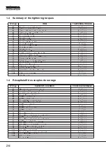
Page 26: ...12 Srew coupling pin screws 30 35 Nm Gear fixing nuts 25 30 Nm 1 4 Récapitulatif des couples de serrage N Chap ÉLÉMENTS À SERRER COUPLE DE SERRAGE 4 3 Axe de tendeur de chaîne automatique 18 20 Nm 4 5 Écrou et contre écrou couronne direction 30 35 Nm 4 6 Contre écrous joints tirants direction 25 30 Nm 4 6 Écrous fixation joints direction 35 40 Nm 4 8 Vis fixation lame gauche 45 50 Nm 4 8 Vis fixat...

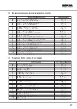
Page 27: ...1 Befestigungsschrauben der Messerplatte 30 35 Nm 6 11 Befestigungsmuttern der Messerwellen Lagergehäuse 25 30 Nm 6 12 Außenmutter zur Befestigung des Spanners 30 35 Nm 6 12 Schraubenbolzen des Spanners 30 35 Nm Befestigungsmuttern der Gangschaltung 25 30 Nm 1 4 Riepilogo delle coppie di serraggio PARTICOLARE COPPIE DI SERRAGGIO 4 3 Albero tendicatena perno galoppino 18 20 Nm 4 5 Dado e controdado...

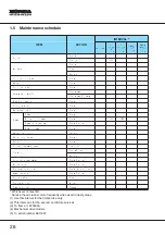
Page 28: ...rake pedal freeplay Check adjust Parking brake Check Blade bolts condition Inspect Blade bolt tightness Check Blade condition Check Front and rear axle grease one pump Spark plug Check clean Replace Clutch pedal freeplay 4 Check adjust Throttle cable Check adjust Fuel tank line and filter Check replace if needed Valve clearance Check adjust Engine fins shroud Clean Chain tension 5 Adjust Drive ped...

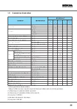
Page 29: ...frein Vérifier et régler Frein à main Vérifier État des boulons de lame Inspecter Serrage des boulons de lame Vérifier État de la lame Vérifier Graissage de l essieu avant et arrière Un coup de pompe à graisse Bougie Vérifier et nettoyer Remplacer Course libre de la pédale d embrayage 4 Vérifier et régler Câble des gaz Vérifier et régler Réservoir à essence durite et filtre Vérifier remplacer au b...

Page 30: ...prüfen Zustand der Messerschrauben Inspizieren Sitz der Messerschrauben Überprüfen Zustand des Messers Überprüfen Schmierfett der Voder und Hinterachse Einmal pumpen Zündkerze Überprüfen und reinigen Ersetzen Spielraum des Kupplungspedals 4 Überprüfen und einstellen Gaszug Überprüfen und einstellen Kraftstofftank Leitung und Filter Überprüfen ggf ersetzen Ventilabstand Überprüfen und einstellen Kü...

Page 31: ...llare e registrare Freno a mano Controllare Condizione viti lame Ispezionare Serraggio viti lame Controllare Condizioni delle lame Controllare Ingrassaggio assale ant e post Applicare grasso Candela Controllare e pulire Sostituire Gioco pedale frizione 4 Controllare e registrare Cavo acceleratore Controllare e registrare Serbatoio tubazioni e filtro Controllare sostituire se necessario Gioco valvo...

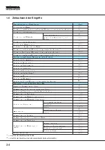
Page 32: ... min Disassembly of engine 12 min Disassembly of cutting plate 13 min Dismantling of pump Hydrostatic drive models 22 min Repairs and or parts replacements Replacement of tyres and wheels each 2 min Replacement of front wheel bearings each 2 min Replacement of steering pinion and gear 8 min Replacement of drive belt 8 min Replacement of blade drive belt 5 min Replacement of cutting plate belt 5 mi...

Page 33: ... 5 min Démontage réservoir 2 min Démontage moteur 12 min Démontage plateau de coupe 13 min Démontage pompe Modèles à transmission hydrostatique 22 min Interventions de réparation et ou de remplacement Remplacement roues chacune 2 min Remplacement roulements avant chacun 2 min Remplacement pignon et couronne 8 min Remplacement courroie de transmission 8 min Remplacement courroie d entrainement lame...

Page 34: ... des Armaturenbretts 5 min Ausbau des Kraftstofftanks 2 min Ausbau des Motors 12 min Ausbau des Mähwerks 13 min Ausbau der Pumpe Modellen mit hydrostatischem Antrieb 22 min Reparatur und oder Austauscheingriffe Reifen und Radwechsel pro Rad 2 min Auswechseln der Kuggellager der vorderen Räder 2 min Ausbau des Kegelrads und des Kranzes der Lenkung 8 min Auswechseln der Treibriemen 8 min Auswechseln...

Page 35: ...ntaggio del cruscotto 5 min Smontaggio del serbatoio 2 2 min Smontaggio del motore 12 min Smontaggio del piatto di taglio 13 min Smontaggio pompa Modelli con trasmissione idrostatica 22 min Interventi di riparazione e o sostituzione Sostituzione ruote cad 2 min Sostituzione cuscinetti ant cad 2 min Sostituzione pignone e corona 8 min Sostituzione cinghia trasmissione 8 min Sostituzione della cingh...

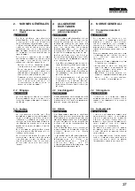
Page 36: ...g that other persons cannot accidentally carry out actions that may physically endanger whoever is working on the lawn tractor 2 2 Slings The lawn tractor must never be lifted using a hoist or other lifting equipment which uses ropes 2 3 Lifting The Lawn Tractor can be lifted by the front section using a jack placed under the lower section of the chassis and with a wooden block 1 between the jack ...

Page 37: ...m Falle von Eingriffen an den Messern oder beim Behandeln von Blechteilen Sich vergewissern daß andere Personen keine Aktionen unbeabsichtigt ausüben können welche die Unversehrtheit der arbeitenden Person beein trächtigen könnten 2 2 Anschlaggerät Der Aufsitzmäher darf niemals mit Hilfe eines Flaschenzugs oder eines anderen Hebemittels bei dem Seile verwendet werden angehoben werden 2 3 Heben Der...

Page 38: ...sary to remove the battery To ensure proper stability pressure must be applied on the rear plate 3 and the collecting bin only 4 taking care not to damage them In the models equipped with an emptying device the grass catcher must be removed the pegs on the forks of the two struts dismantled and the grass catcher release lever moved to the full forward position C Insert a wedge 3 of about 40 mm und...

Page 39: ...icht mehr erforderlich sein Um ausreichende Stabilität zu gewährleisten darf sich das Gewicht nur auf die Heckplatte 3 und die Halterungen der Grasfangbox 4 verteilen Dabei ist darauf zu achten daß diese nicht beschädigt werden Bei Modellen mit Vorrichtung zum Entleeren des Sacks müssen der Sack herausgenommen die Stifte der Gabeln der beiden Gasfedern ausgebaut und der Hebel zum Ausklinken des Sa...

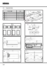
Page 40: ...OLS NAME REF 1 Block CG60700000H0 steel 2 Block CG60700001H0 steel 3 Guide CG60800030H0 steel 4 Guide CG60800031H0 nylon 5 Puller CG60253000H0 steel 6 Gauge CG60205000H0 steel 7 Checkers CG60205001H0 steel CG60208000H0 40 ...

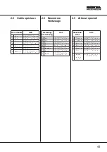
Page 41: ...000H0 Stalh 2 Keil CG60700001H0 Stalh 3 Führung CG60700030H0 Stalh 4 Führung CG60700031H0 Nylon 5 Auszieher CG60253000H0 Stalh 6 Form CG60205000H0 Stalh 7 Tester CG60205001H0 Stalh CG60208000H0 2 5 Attrezzi speciali Denomina zione REF 1 Spessore CG60700000H0 acciaio 2 Spessore CG60700001H0 acciaio 3 Tampone CG60700030H0 acciaio 4 Tampone CG60700031H0 nylon 5 Estrattore CG60253000H0 acciaio 6 Calib...

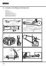
Page 42: ...2 6 Summary of main fittings and checking values 1 Frame 2 Cutting deck 3 Steering geometry 4 Transmission belt extension 5 Blade drive belt extension 6 Cutting plate belt extension 42 ...

Page 43: ...roie du plateau de coupe 2 6 Zusammenfassung der wichtigsten Montagemaße und Überprüfung 1 Fahrgestell 2 Mähwerk 3 Lenkgeometrie 4 Verlauf des Getrieberiemens 5 Verlauf des Meßerantriebsriemens 6 Verlauf des Mähwerkriemens 2 6 Riepilogo delle principali quote di montaggio e verifica 1 Telaio 2 Piatto di taglio 3 Geometria dello sterzo 4 Sviluppo cinghia trasmissione 5 Sviluppo cinghia guida lame 6...

Page 44: ...ot always capable of performing For this reason the assistance centre must do everything necessary to ensure that the equipment functions perfectly and may take the following steps 1 Tuning the lawn tractor every time possible 2 Proposing a regular maintenance programme to the customer to be carried out at pre arranged intervals for example at the end of the summer or prior to a long period of ina...

Page 45: ...liche tun um eine einwandfreie Funktion des Geräts sicherzustellen hierzu bieten sich folgende Möglichkeiten 1 Bei jeder sich bietenden Gelegenheit eine R e g u l i e r u n g d e s A u f s i t z m ä h e r s vorzunehmen 2 D e m K u n d en e i n P r o g r a m m d e r periodischen Wartung vorzuschlagen das in vorbestimmten Zeitabständen durchgeführt wird zum Beispiel am Ende d e r S a i s o n o d e r...

Page 46: ...f the control lever Should this be the case first clean the lever joint otherwise the tensionner could be incorrectly adjusted a Cleaning the lever joint 1 This operation can be carried out via an inspection door and can also be made easier by removing the conveyor see 5 3 2 Having reached the lever joint 1 remove the accumulated grass cuttings 2 which stop the lever from reaching the end b Tensio...

Page 47: ...anner eingestellt werden Die Schwierigkeit des Ausschaltens kann auch von erhöhten Grasablagerungen am Endanschlag des Hebels verursacht sein In diesem Fall muß zuerst der Anschlag des Hebels gereinigt werden um eine unnuetze Einstellung des Spanners zu vermeiden a Reinigung des Hebelgelenks 1 D i e s e A r b e i t k a n n ü b e r d i e W a r t u n g s a b d e c k u n g d u r c h g e f ü h r t wer...

Page 48: ...her of the holes on the lever Bear in mind that 1 If this length is too great spring tighter this causes sudden engagement of the drive which may raise the front wheels 2 If this length is too short spring slacker the belt slips under the load so reducing power in forward motion An inspection door also provides access to the brake spring 2 that can be adjusted by the nut 3 located at the end of th...

Page 49: ...106 mm Diese Länge erhält man durch Benutzung einer der beiden vorgesehenen Bohrungen Es ist zu beachten daß 1 Eine zu große Federlänge größere Vorspannung zu ruckartigem Einkuppeln führt dabei können die Vorderräder abheben 2 B e i e i n e r z u g e r i n g e n Fed erl ä n g e geringere Vorspannung der Riemen unter Last durchrutscht und damit die Antriebsleistung nachläßt Die Bremsfeder 2 ist ebe...

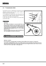
Page 50: ...n the tightener 2 and the locknut 3 Correct the tension on the chain with screw 4 without overtightening Correct tightening is obtained by checking against arrow A 5 6 mm via the inspection door When the adjustment has been made fully tighten the nut on the tightener 2 and the locknut 3 Tightening torque 2 Guide pulley spindle 8 20 Nm HF2213k1 HF2218 These machines are equipped with an automatic d...

Page 51: ...s Spanners sowie die Ko n te r mut t e r 3 lösen Die Kettenspannung nicht zu stramm mit der Schraube 4 einstellen Die korrekte Spannung ist erreicht wenn d er Durchhang A an der Wartungsabdeckung 5 6 mm beträgt Nac h A bsch lu ß d e r E in ste llung Spannermutter 2 und Kontermutter 3 vollständig festziehen Anzugsdrehmomente 2 Bolzen der Leitrolle 18 20 Nm HF2213K1 HF2218 Diese Maschinen sind mit e...

Page 52: ...repeated with the deck positioned at two or three different cutting heights b Complete adjustment 1 Put the lawn tractor on a level firm and flat surface on a work bench for example Put some blocks beneath the cutting deck corresponding to the centre of the blades front 25 mm 2 Tool n CG60700000H0 rear 28 mm 3 Tool n CG60700001H0 2 Set the cutting height adjustment lever to position 1 and fully lo...

Page 53: ...isch Unter das Mähwerk sind Unterlegscheiben übereinstimmend mit der Mittellinie der Messer zu legen vorne Stärke von 25 mm 2 Werkzeuge Nr CG60700000H0 hinten Stärke von 28 mm 3 Werkzeuge Nr CG60700001H0 2 Den Schnitthöhen Einstellhebel auf Position 1 stellen und die beiden Einstellvorrichtungen 1 Muttern 4 und Kontermuttern 5 der vier Gelenkstangen vollständig lösen bis das Mähwerk auf den Blöcke...

Page 54: ... the pinion ring gear coupling unscrew the nut 1 and the locknut 2 When the central screw 3 which holds the ring gear 4 is undone remove one or both of the spacers 5 placed between the bush 6 and the frame Re assemble everything fully tightening the nut and locknut 1 and 2 If the movement remains despite having removed the spacers check and if necessary replace the pinion ring gear unit or look fo...

Page 55: ... n g Kegelrad Kranz zurückzuführen ist die M u t t e r 1 u n d d i e G e g e n m u t t e r 2 ausschrauben Nach dem Ausschrauben der Zentralschraube 3 die den Kranz 4 hält eine oder beide Ausgleichscheiben 5 die sich zwischen der Buchse 6 und dem Fahrgestell befinden herausnehmen Alles wieder einbauen Mutter und Gegenmutter 1 und 2 festziehen Wenn die Störung anhält nachdem alle Ausgleichscheiben e...

Page 56: ...ustment 1 To obtain perfect parallelism the distance measured between the centres of the joints 1 of the wheel connecting shaft 2 must be 516 5 mm 2 On assembly fully tighten the locknuts 3 and the fastening nuts 4 of the heads b Adjustment of the steering wheel 1 Firstly check the toe in point a and align the front wheels 2 If the steering wheel is not straight remove the joint 5 and screw it int...

Page 57: ...t zu prüfen ob sich die Befestigungen der Gelenke gelöst haben a Regulierung der Vorspur 1 Zur Erreichung einer vollkommenen Parallelität muß der zwischen den Mittelpunkten der Gelenkköpfe 1 der Spurstange 2 gemessene Abstand genau 516 5 mm betragen 2 Bei der Montage die Gegenmutter 3 und die Befestigungsmuttern 4 der Köpfe festziehen b Einstellung des Lenkrads 1 Zuerst die Vorspur prüfen Punkt a ...

Page 58: ...the cutting edges of the two blades close together in the various possible upper and lower positions A A1 B B1 A B1 B A1 They must be aligned to within 2 mm If the values measured are higher it should be checked that the blades are not deformed If this is not the case the blade shafts should be checked and replaced if necessary see 6 11 and the positioning of the blade shaft journal bearings on th...

Page 59: ...ube beachten 1 siehe 4 8 3 Die Schneidkanten der beiden Messer in den verschieden möglichen oberen und unteren Positionen A A1 B B1 A B1 B A 1 n a h e z u s a m m en s t el l en D i e maximale Abweichung darf 2 mm nicht überschreiten Sind die gemessenen Werte höher die Messer auf Verformung kontrollieren Ist dies nicht der Fall die Messerwellen überprüfen und ggf erneuern Siehe 6 11 Außerdem die P...

Page 60: ... 2 The screw for the right blade 1b has a right hand thread and is unscrewed in an anti clockwise direction a Sharpening 1 Both cutting edges of a blade must always be sharpened on the bevelled side only and no further than the 10 mm maximum blade wear level 2 b Balancing 1 Check the balance using the appropriate equipment until there is a maximum difference of 2 grammes between one side and the o...

Page 61: ...rsinn ausgeschraubt wird 2 Die Schraube des rechten Messers 1b e i n R e c h t s g e w i n d e h a t u n d i m e n t g e g e n g e s e t z t en U h r z e i g er s i n n ausgeschraubt wird a Schärfen 1 Es müssen immer beide Schneidkanten des Messers ausschließlich auf der abgeschrägten Seite geschärft werden die Verschleißgrenze von 10 mm darf hierbei nicht überschritten werden 2 b Auswuchten 1 Die...

Page 62: ...access remove also the cover for the electronic card and the wire connections 2 The adjustment is made with the nut 1 Screwing the nut down on the rod increases the braking capacity 3 With the pedal completely pressed and the parking brake engaged the spring 2 length should be 115 117 mm A measured from the inner part of the washer Do not exceed these values to avoid overloading the brake unit A S...

Page 63: ...uch den Schutz der elektronischen Platine ausbauen und die Verbinder trennen 2 Die Justierung erfolgt mit Hilfe der Mutter 1 durch Einschrauben der Mutter auf der Stange erhöht man das Bremsvermögen 3 Bei völlig durchgedrücktem Pedal und angezogener Feststellbremse muß die Länge der Feder 2 gemessen zwischen d e n S c h e i b e n 1 1 5 1 1 7 m m betragen A Diese Werte dürfen nicht überschritten we...

Page 64: ...s may be caused by a change in length of the belt It will therefore be necessary to adjust the screw coupling 1 Put the lawn tractor into a vertical position see chap 2 4 2 Position the end of the screw coupling spring 1 in one of the three holes on the lever 2 in order to reach the indicated length A measured from the outer part of the eyelets A Spring length 145 154 Nm 64 ...

Page 65: ...e vorgenommene Veränderung der Länge des Treibriemens verursacht sein In diesem Fall ist der Spanner einzustellen 1 Den Aufsitzmäher senkrecht stellen siehe Kapitel 2 4 2 Das Ende der Feder 1 des Spanners in eine der auf dem Hebel 2 vorgesehenen Bohrungen so einsetzen daß man das angegebene Maß gemessen von der Außenseite der Ösen erhält A Länge der feder 145 154 mm 4 10 Regolazione cinghia trazio...

Page 66: ...the distance between the articulated joint 5 and the fork 6 of the control rod is 133 134 5 mm A Having checked and adjusted the length ensure that the two locknuts 7 for the articulated joint and the fork are fully tightened 2 At this distance the position of the pedal in neutral N compared to the footboard should be as shown in the drawing c Adjusting the neutral position This is a very importan...

Page 67: ... e r Achsabstand zwischen dem Gelenk 5 und der Gabel 6 der Steuerungsstange 133 134 5 mm ist A nachdem man das Maß überprüft und eventuell neu e i n g e s t e l l t h a t m u ß m a n s i c h v e r g e w i s s er n d a ß d i e b e i d e n Gegenmuttern 7 des Gelenks und der Gabel gut festgezogen sind 2 Wenn dieses Maß eingehalten wird muß die Position des Pedals in Leerlaufstellung in Bezug auf die ...

Page 68: ...ernal components Whether or not this will be useful is at the discretion of the mechanic s experience The timings for these items of work are shown in chapter 1 6 5 1 Removal of front hood The removal of the front hood gives greater accessibility to the engine and its accessories the silencer and protection Free the cables 1 from the cable clamp and remove the bulbs 2 by unscrewing them in the ant...

Page 69: ...l i c h k e i t d i e s e O p e r a t i o n e n vorzunehmen wird der Entscheidung und der Erfahrung des Mechanikers überlassen Der Zeitaufwand für diese Arbeiten ist in Kapitel 1 6 wiedergegeben 5 1 Ausbau der vorderen motorhaube Der Ausbau der vorderen Motorhaube erleichtert den Zugang zu folgenden Teilen dem Motor und den dazugehörenden Bauteilen dem Schalldämpfer und den Schutzvorrichtungen Die...

Page 70: ...move the cover caps from the springs 4 unscrew the pins 5 and the screws 6 which are located under the side footboards and the rear screws 7 3 Place the cutting height adjusting lever in position 7 and the clutch lever in the blades engaged position then remove the wheel cover 8 taking care to mark the direction of installation of the switch wires 9 before disconnecting them If you prefer to remov...

Page 71: ... verursachen die Batterie 2 abklemmen und herausnehmen 2 Den Knauf 3 des Kupplungshebels abschrauben die Abdeckungen der Federn 4 herausnehmen die Bolzen 5 und die Schrauben 6 die unter den s e i t l i c hen T r it t b ret t er n a n geb r a c h t sind und die rückseitigen Schrauben ausschrauben 7 3 Den Schnitthöhen Einstellhebel auf 7 stellen und den Kupplungshebel in die eingekuppelte Position b...

Page 72: ...e replaced 1 Undo the internal screws 1 fixing it to the rear plate and then unhook the small retaining springs 2 which hold it to the cutting deck Slide out the conveyor 3 resting it on the lower edge of the plate so that the side fins will pass 4 2 When re assembling grease the joints well and do up the screws 1 without fully tightening in order to allow the free movement of the conveyor 72 ...

Page 73: ...er hinteren Platte ausschrauben und die Halteklammern 2 die den Förderer auf dem Mähwerk befestigen aushaken den Förderer 3 herausziehen wobei er auf der unteren Kante der Platte abgestützt gehalten wird um den Durchgang der seitlichen Flügel 4 zu ermöglichen 2 Bei der Montage sind die Verbindungen gut zu schmieren und die Schrauben 1 einzudrehen ohne sie fest anzuziehen um die Bewegung des Förder...

Page 74: ...cables 4 before disconnecting them If you prefer to remove the switch without disconnecting the electric wires it must be correctly positioned when reinstalling so that it operates correctly see 7 10 For models with a grass catcher emptying device the end of the rod 5 will need to be taken off the lever 6 and the white wire 7 for the microswitch 8 signalling a full grass catcher together with the ...

Page 75: ...Die Platte ausbauen und darauf achten die Position der Schalterkabel 4 vor dem Abziehen zu kennzeichnen Bleiben beim Ausbau des Schalters die Kabel angeschlossen den Schalter beim Wiedereinbau so positionieren daß er ordnungsgemäß funktioniert siehe 7 10 Bei Modellen mit Vorrichtung zum Entleeren des Sacks muß man das Ende der Stange 5 des Hebels 6 herausziehen und außerdem das weiße Kabel 7 des M...

Page 76: ...es from the gauge 2 b Dashboard 1 Use a 5 mm diameter pin drift to drive out the pin 5 and remove the steering wheel Then remove the gear lever 6 with a wrench up to serial n 8700011 From serial n 8700012 just unscrew the knob on the gear lever NOTE On hydrostatic drive models there is no gear lever 2 Disconnect the end of the throttle cable from the engine disconnect all the electric connections ...

Page 77: ...ausdrehen nachdem die Kabel vom Kraftstoffstandgeber 2 abgezogen wurden b Armaturenbrett 1 Mit einem 5 mm Treibdorn den Stift 5 austreiben und das Lenkrad abnehmen Anschließend den Schalthebel 6 mit einem Schlüssel abs chrauben bis Seriennummer 8700011 Ab S eri enn um m er 8 70 0 0 1 2 ist es ausreichend den Griff des Ganghebels abzuschrauben ANMERKUNG B e i M o d e l l e n m i t hydrostatischem A...

Page 78: ...ectric wires Take off the fuel hose taking care not to allow any petrol leak Find and undo all the screws fastening the engine to the frame Hold on firmly to the engine and lift taking care when doing so NOTE Some types of engine are provided with attachment by screws of different lengths and different positions It is therefore a good idea to mark them to avoid any mistake during reassembly 1 On r...

Page 79: ... Auspuffabdeckung 5 demontieren und alle Seilzüge und elektrischen Leitungen lösen Den Kraftstoffschlauch lösen darauf achten daß kein Kraftstoff ausläuft Nachdem alle Schrauben zur Befestigung des Motors am Fahrgestell festgestellt und gelöst worden sind den Motor mit der gebotenen Sorgfalt fest umgreifen ANMERKUNG Die Länge und Position der Motorbefestigungsschrauben variiert bei einigen Motorty...

Page 80: ...the cutting height adjusting lever in position 1 and then unscrew the upper nut on the lifting cable adjusting devices 1 and remove them from their seats by slightly raising the plate 4 Loosen the clutch cable 2 and remove it from its seat Remove the upper casing 3 and unhook the spring 4 from the tightener 5 Unscrew the nuts 5 and the locknuts 6 of the jointed connecting rods and remove the deck ...

Page 81: ... s t e l l e n d i e o b e r e M u t t e r d e r Hubseileinsteller 1 lösen und diese unter leichtem Anheben des Mähwerks aus den Halterungen aushängen 4 Den Einsteller des Kupplungszuges 2 l ö s e n u n d a u s h ä n g e n D a s Gehäuseoberteil 3 demontieren und die Feder 4 am Spanner aushängen 5 Die Muttern 5 und die Gegenmuttern 6 der Gelenkpleuelstangen ausschrauben und das Mähwerk ausbauen B e...

Page 82: ...mbly Dismantle the articulated joint 2 of the control rod from the pump lever 5 Unhook the brake return spring 3 and unscrew the locknut 4 so that the rod 5 is free to run forwards 6 Put the lawn tractor in a vertical position see chap 2 4 7 To remove the pump undo the two lower screws 6 fixing on the support 8 and the two upper screws 7 which attach the pump to the frame Hold up the pump so that ...

Page 83: ...er Steuerungsstange des Pumpenhebels ausbauen 5 D i e R ü c k h o l f e d e r 3 d e r B r e m s e aushaken und die Gegenmutter 4 so lösen daß sich die Stange 5 frei nach vorne bewegen kann 6 Den Aufsitzmäher senkrecht stellen siehe Kapitel 2 4 7 Um die Pumpe herauszunehmen genügt es die beiden unteren Befestigungß chrauben 6 der Halterung 8 und die beiden oberen Schrauben 7 welche die Pumpe am Fah...

Page 84: ...he cutting deck should be checked to ensure that it is parallel see 4 4 Replace deformed wheel rims in order to ensure satisfactory performance of the tyres a Front wheels 1 The front wheels are held by retaining ring 1 that can be removed with a screwdriver 2 When fitting smear the pin with grease and replace the shouldered washer 2 b Rear wheels NOTE If a wheel is jammed on the axle use a penetr...

Page 85: ... es immer angebracht die Parallelität des Mähwerks zu kontrollieren siehe 4 4 Beschädigte Felgen sind zu erneuern um eine einwandfreie Funktion der Reifen zu gewährleisten a Vordere Räder 1 D i e V o r d e r r ä d er s i n d m it Sicherungsscheibe 1 befestigt die mit einem Schraubendreher entfernt werden können 2 B e i m E i n b a u den B o lz en m it Fet t schmieren und die Schulterscheibe 2 erne...

Page 86: ...e Tool n CG82000591H1 are interchangeable with the type previously used and make it easier to remove the wheel From serial n 8800001 1 The rear wheel is no longer fixed by the screw 4 and nut 5 but is the same as the front wheel using a snap ring 1 and a shoulder washer 2 Tightening torque 5 Rear wheel nut 20 25 Nm Tyre pressures Front 1 5 Bar Rear 1 2 Bar 86 ...

Page 87: ...0 0 0 5 9 1 H 1 k ö nnen m it den v o r a u s g eh en d e n A u s f ü h r u n gen ausgewechselt werden und erleichtern den Ausbau des Rades Ab Seriennummer 8800001 1 Die Befestigung des hinteren Rades sieht nicht mehr die Schraube 4 und die Mutter 5 vor sondern erfolgt mit Hilfe eines Sp rengr ings 1 und einer Bundscheibe 2 wie beim Vorderrad Anzugsdrehmomente 5 Mutter der hinteren Räder 20 25 Nm ...

Page 88: ...nt wheel hub 3 Bearings are driven out by fitting a 10 to 12 mm diameter rod 1 from the opposite side and striking all around the inside circumference of the bearing with a hammer 4 The new bearing must be inserted with the help of a plastic mallet or a nylon pad 2 Tool n CG60800031H0 working only on the outer ring of the bearing 88 ...

Page 89: ...in S t a h l d o r n 1 v o n 10 1 2 m m D u r c h m es s er v o n d er gegenüberliegenden Seite aus eingeführt und das Lager durch Hammerschläge ü b e r d e n g e s a m t e n U m f a n g d es Lagerinnenrings ausgetrieben 4 Das neue Kugellager ist mit Hilfe eines Kunststoffhammers oder mit einem N ylonstopfen 2 Werkzeuge Nr CG60800031H0 der nur auf den äußeren Ring d es Kugellagers einwirkt einzuse...

Page 90: ...ottom of the tube itself 4 Dismantle the articulated joint 8 of the ring gear 9 unscrew the nuts 10 and 11 and remove the lower central screw 12 5 Assemble the pinion and the ring gear lining up the two reference points è t punched on them With a new pinion and ring gear it is necessary to assemble two 0 8 mm spacers 13 Tool n CG22672150H0 between the ring gear bush and the frame 6 Reassemble ever...

Page 91: ...d er Gangschaltung 5 festzuhalten und darauf zu achten daß die Achsbuchse 7 unten am Rohr nicht herausgeht 4 Das Gelenk 8 des Kranzes 9 ausbauen die Muttern 10 und 11 ausschrauben und die untere Zentralschraube 12 herausziehen 5 Kegelrad und Kranz so montieren daß die beiden darauf eingeprägten Bezugs markierungen è t übereinstimmen Beim Einbau eines neuen Kegelrads mit Kranz müssen zwei Ausgleich...

Page 92: ... clutch pulley 1 by unscrewing the central nut 2 Then completely unscrew the nut 3 on the drive engagement tightener 4 to make it easier to fit the new belt 4 When re assembling check the precise position of the belt compared to the pegs and the runners see 2 6 5 Carry out the drive engagement adjustments see 4 2 Tightening torque 2 Transmission pulley fixing nut 35 40 Nm 3 Clutch tightening nut 2...

Page 93: ...en der Befestigungsmutter 2 ausbauen Dann die Mutter 3 der A n t r i eb s k u p p l u n g s S p a n n r o l l e 4 v o l l s t ä n d i g a b s c h r a u b en um d a s A u f l eg en d e s n euen Riem ens z u erleichtern 4 Bei der Montage muß die korrekte Stellung des Treibriemens zu den Haken und den Halterungen siehe Kap 2 6 überprüft werden 5 Die Einstellung der Antriebskupplung vornehmen siehe 4 ...

Page 94: ...n the engaged position to free the brake from the pulley Remove casings where present 3 Undo the screw 1 and remove the control pulley 2 Loosen the nut 3 almost completely without removing the tightening pulley 4 4 When fitting carefully replace the belt with respect to the guides and slides see 2 6 5 Regulate the blade engagement lever see 4 1 Tightening torque 1 Pulley fixing screw 20 25 Nm 3 Gu...

Page 95: ...n und den Schalthebel der Messer auf Einschaltung stellen damit die Bremse der Riemenscheibe gelöst wird Den Riemenschutz wo vorgesehen abnehmen 3 Die Schraube 1 herausdrehen und die Antriebsriemenscheibe 2 abnehmen Die Mutter 3 fast ganz abschrauben die Spannrolle 4 wird nicht ausgebaut 4 Beim Auflegen des neuen Riemens auf die k o r rek te V erl egu ng in nerh al b d er Führungen und Gleitschien...

Page 96: ...gth of the tightening screw 9 which must be restored during fitting in order to provide preliminary adjustment of the belt and unscrew it fully 6 Remove guide 10 loosen guide 11 and the pulley 12 so that the belt can be removed 7 Remove the new belt so that with two strands tightened the blades are positioned at an angle of 90 one with respect to the other 8 Reinstall all the parts by carrying out...

Page 97: ... n d eins t el lu ng d es Riemen s wiederhergestellt werden und die Schraube ganz herausdrehen 6 D i e F ü h ru ng 1 0 a b s c hr au ben Führung 11 und Riemenscheibe 12 lösen so daß der Riemen abgenommen werden kann 7 Den neuen Riemen so auflegen daß w en n die beid en la n gen Riemenabschnitte gespannt sind die M es s er i n einem W ink el v o n 9 0 zueinander stehen 8 Der Zusammenbau erfolgt in ...

Page 98: ... of 3 5 kg for HF2213 4 2 kg for HF2218 Adjust the tightening screw 9 page 88 until this value is obtained 2 Reinstall the casing the tightener and the transmission belt checking that they are correctly positioned with respect to the notches and guides see Chapter 2 6 3 Check the adjustment of the blade engagement lever see 4 1 Tightening torque 2 Blades pulley fixing screw 20 25 Nm 5 Coupling pla...

Page 99: ...is 10 mm beträgt 3 5 kg für HF2213 4 2 kg für HF2218 Die Spannschraube 9 Seite 89 solange drehen bis der vorgeschriebene Wert erreicht ist 2 Gehäuse Spanner und Getrieberiemen wieder einbauen dabei darauf achten daß diese im Hinblick auf die Nuten und Führungen richtig positioniert sind siehe Kapitel 2 6 3 Die Einstellung des Schalthebels der Messer durchzuführen siehe 4 1 Anzugsdrehmomente 2 Schr...

Page 100: ...es provided on the nuts 6 This ring gear and the nuts ensure precision during assembly b Replacement of bearings The bearings are secured axially to the half axles by means of two clamping collars 7 When fitting it is advisable to allow the bearings to slide freely on the shaft fit the chain on the ring gear and on the gearbox pinion reinstall the bearing flanges and their corresponding screws wit...

Page 101: ...en für die an den Muttern 6 befindlichen Zentrieransätze versehen wodurch eine präzise Positionierung beim Zusammenbau erreicht wird b Auswechseln der Kugellager Die Lager sind in axialer Richtung mittels zweier Halteringe 7 an den Achswellen befestigt Beim Einbau sollten die Lager frei auf den Wellen gleiten können Die Kette auf das Kettenrad und das Getrieberitzel auflegen die Lagerflansche und ...

Page 102: ... loosen the nut 2 on the return pulley 3 enough to be able to remove the cable 4 3 On reinstalling place the cutting plate at maximum height fit the cable in the spline on the toothed section and place the end of the cable in a Z shape 5 in its housing 4 Route the cable correctly fit the adjusting device 1 and then screw the pulley nut 2 without locking 5 Adjust the deck so that it is parallel wit...

Page 103: ...ängen und die Mutter 2 an der Umlenkrolle 3 soweit lösen daß das Seil 4 ausgehängt werden kann 3 Beim Einbau das Mähwerk auf die maximale Höhe stellen das Seil in die Längsnut der Verzahnung einlegen und das z förmige Ende 5 korrekt in die Bohrung einhängen 4 D a s S eil ko r rek t v er leg en den Einsteller 1 anbringen und die Mutter 2 der Umlenkrolle anbringen ohne sie festzuziehen 5 Die Paralle...

Page 104: ...ove it from its seat and unhook the spring 2 4 Remove the end of the cable 3 from the fork 4 located on the lever hinge and remove the cable 5 5 After reinstalling the cable adjust the engagement of the blades see 4 1 6 10 Replacing the throttle lever 1 Detach the end of the cable from its cable stop on the engine side 2 Using a socket wrench inserted in the cable passage slot undo the two fixing ...

Page 105: ...1 lösen aus der Halterung nehmen und die Feder 2 aushängen 4 D e n S e i l z u g n i p p e l 3 a us d em G a b e l k o p f 4 a m H eb elg el enk a u s h ä n g e n u nd den S eil z ug 5 herausnehmen 5 Nach Einbau des neuen Zuges die Messerkupplung einstellen siehe 4 1 6 10 Auswechseln des Gashebels 1 Das motorseitige Gaszugende aus der Halterung lösen 2 Mit Hilfe eines Rohrschlüssels der in den Sch...

Page 106: ...he plate 2 and remove it 5 Remove the journal bearing by unscrewing the three fixing nuts 3 The journal bearing with the shaft and the bearings is available in the form of a set of spare parts Should you wish to replace the shaft or the bearings alone hit the shaft on the pulley side with a plastic mallet for removing the shaft together with the lower bearing 6 After removing the retaining rings 4...

Page 107: ...festigungsschrauben 3 des Fl a ns c h es a us s c h ra ub en und den Flansch ausbauen Der gesamte Flansch zusammen mit Wellen und Kugellagern ist als Ersatzteil in Fo rm einer montierten Gruppe lieferbar Wenn man nur die Welle oder die Kugellager a u s w ec h s e l n m ö c ht e m it ein em Kunststoffhammer von der Seite d er Riemenscheibe her auf die Welle klopfen um die Welle zusammen mit dem unt...

Page 108: ... using a suitable guide Tool n CG60800030H0 10 and acting on the inner bush Strike with a hammer until the bearing is perfectly positioned 9 Fit the journal bearing without completely tightening the screws 3 which will only be tightened after fitting the plate whose holes must be centred around the upper section of the journal bearing 11 Tightening torques 1 Plate fixing screws 30 35 Nm 3 Flange f...

Page 109: ...hrung Werkzeuge Nr CG60800030H0 10 auf dem Innenring mit dem Hammer in Einbauposition treiben 9 Das Lagergehäuse anbringen ohne die Schrauben 3 endgültig festzuziehen diese werden erst nach dem Anbringen des Mähwerks festgezogen da dessen Bohrungen um den oberen Abschnitt des Lagergehäuses 11 herum zentriert werden müssen Anzugsdrehmomente 1 Schrauben zur Befestigung der Platte 30 35 Nm 3 Muttern ...

Page 110: ...y to dismantle the spring or the arms loosen the screw 2 and make the replacements 4 On re assembly meticulously follow the order of the various components and ensure that when the internal nut 3 is blocked the two arms are free to float 5 Re fit the chain tensioner making sure that the pinions work with the chain as shown in the figure Fully tighten the external nut 1 and check that there is a di...

Page 111: ...r Arme erforderlich ist ist die Schraube 2 zu lösen und der notwendige Austausch vorzunehmen 4 Bei der Montage muß unbedingt die Reihenfolge der verschiedenen Bauteile genau eingehalten werden Man muß sich vergewissern daß sich die beiden Arme bei fest angezogener Innenschraube 3 frei bewegen ohne anzustoßen 5 Den Spanner wieder einbauen und sich dabei vergewissern daß die Ritzel auf der Kette arb...

Page 112: ...ly charged after several attempts at starting Recharge the battery Wet card with or without alarm Check and dry with low force warm air In subsequent use when the key is inserted in the position ON with or without alarm Short circuit on the earthing of equipment signals or safety systems with audio signal Check circuits and leads In the START position or after a few seconds of use with alarm Corro...

Page 113: ...t disconnected Check for draining of charge caused by worn insulation on leads Check that regulator is working efficiently see 7 8 Loose earth connection to regulator HF2218 Check earth connection to regulator 9 The LEDs come on in an abnormal and uncontrolled manner The PCB operates irregularly The PCB is damp Dry with low force warm air Loose earth connection Check and put right 10 On engaging b...

Page 114: ... la position ON avec ou sans bip sonore Court circuit au niveau de la masse des équipements des signaux ou des systèmes de sécurité avec bip sonore Contrôler les circuits et les câblages Sur la pos START ou après quelques secondes d utilisation avec bip sonore Raccordements de la batterie oxydés ou peu sûrs Contrôler et nettoyer Fiche mouillée Contrôler et sécher avec un jet d air tiède à basse pr...

Page 115: ...s câbles Contrôler l efficacité du régulateur Masse du régulateur peu sûre HF2218 Contrôler la fixation du régulateur à la masse 9 Les leds s allument de façon anormale et incontrôlée la carte électronique fonctionne de manière irrégulière La carte électronique est mouillée Sécher avec un jet d air tiède et à basse pression Masse peu sûre Contrôler et remettre en fonction 10 A l enclenchement des ...

Page 116: ...Überprüfen und mit lauwarmer Luft mit niedrigem Druck trocknen bei nachfolgendem Gebrauch beim Stellen des Zündschlüssels auf die Po sit i o n ON mi t o der ohne akustischem Signal Masseschluß von Verbraucher Signalen oder Sicherheitssystemen mit akustischem Signal Stromkreise und Verkabelung überprüfen in der Position START oder nach einigen Sekunden in Betrieb mit akustischem Signal Batterieansc...

Page 117: ...e 7 8 Masseanschluß auf dem Regler mangelhaft HF2218 Befestigung des Massekabels des Reglers überprüfen 9 Die LEDs leuchten unnormal und unkontrolliert auf Die Schaltplatine funktioniert abnormal Schaltplatine ist feucht Platine mit lauwarmer Luft mit niedrigem Druck trocknen Masseanschluß Überprüfen und Masseanschluß erneut herstellen 10 Beim Einschalten der Messer stellt der Motor ab Kupplungsvo...

Page 118: ...care la batteria Scheda bagnata con o senza segnalazione Controllare e asciugare con un flusso d aria tiepida a bassa pressione Ne gli ut i li zzi succe ssivi all inserimento della chiave pos ON con o senza segnalazione acustica Corto circuito sulla massa della macchina sui segnalatori o sul sistema di sicurezza con segnale acustico Controllare i circuiti e i cablaggi in pos START o dopo qualche s...

Page 119: ...on isolamento deteriorato Controllare l efficacia del regolatore vedi 7 8 Massa incerta sul regolatore HF2218 Controllare il fissaggio a massa del regolatore 9 I LED si illuminano in modo anormale e incontrollato La scheda funziona in modo irregolare Scheda bagnata Asciugare con un flusso d aria tiepida a bassa pressione Massa incerta Controllare e ripristinare 10 Inserendo le lame il motore si sp...

Page 120: ... makes no difference 7 2 Tableau récapitulatif des interventions des systèmes de sécurité Ce tableau présente les interventions des systèmes de sécurité au cours des différentes situations de travail OPERATEUR BAC DE RAMASSAGE LAMES TRANSMISSION1 FREIN MOTEUR TEMOINS LUMINEUX TABLEAU BRANCHE pos ON Assis OUI OFF 4 ON Éteint o n o o n o n o Assis NON OFF 4 ON Éteint o n o o n n n o DEMARRAGE pos ST...

Page 121: ...eht aus 1 o o n o n o o o 1 Ab Seriennummer 8700001 2 Bei Modellen mit mechanischem Antrieb 3 Bei Modellen mit hydrostatichem Antrieb 4 Posistion ohne Einflußnahme 7 2 Tabella riepilogativa degli interventi dei dispositivi di sicurezza In questa tabella sono riportati gli interventi dei dispositivi di sicurezza nelle varie situazioni di impiego OPERATORE SACCO LAME TRASMISSIONE1 FRENO MOTORE SPIE ...

Page 122: ...ssed SEAT MICROSWITCH 15 16 Free O Pressed 15 17 O Free Pressed BRAKE MICROSWITCH 18 19 Free O Pressed BLADE MICROSWITCH 19 21 O Free Pressed 19 20 Free O Pressed IN NEUTRAL SIGNAL from serial N 8700001 9 1 Free O Pressed GRASS CATCHER FULL SIGNAL from serial N 8700001 22 1 Free O Pressed FUEL RESERVE WARNING LIGHT 15 14 O Reserve Full OIL WARNING LIGHT 10 Earth O Always LIGHTS SWITCH 2 3 22 OFF w...

Page 123: ...to 11 13 O Libero Premuto MICRO SEDILE 15 16 Libero O Premuto 15 17 O Libero Premuto MICRO FRENO 18 19 Libero O Premuto MICRO LAME 19 21 O Libero Premuto 19 20 Libero O Premuto SEGNALATORE FOLLE dalla matr 8700001 9 1 Libero O Premuto MICRO SACCO PIENO dalla matr 8700001 22 1 Libero O Premuto SPIA RISERVA CARBURANTE 15 14 O Riserva Pieno SPIA OLIO 10 Massa O Sempre INTERRUTTORE FARI 2 3 22 OFF con...

Page 124: ...the CN 1 cable connector the lights should come on 7 6 Checking the operation of the star ter relay When a bridge is established between terminals 8 and 6 of the connector 1 on wiring CN 1 actuation of the relay must be actuated and the starter must operate If the relays are actuated but the starter does not operate use a cable with a large cross section 5 mm to establish a bridge 2 between the re...

Page 125: ...el connettore del cablaggio CN1 si devono accendere i fari 7 6 Controllo del funzionamento del relé di avviamento Quando viene effettuato un ponticello tra i terminali 8 e 6 del connettore CN1 il relé si deve attivare e il motorino di avviamento deve funzionare Se il relé viene attivato ma il motorino di avviamento non funziona effettuare un ponticello tra i terminali del relé 2 utilizzanzo un cav...

Page 126: ...l 11 Seat switch Terminal 15 Brake switch Terminal 19 Blade switch Terminal 19 In neutral signal Terminal 9 Grass catcher full microswitch Terminal 22 Petrol reserve indicator Terminal 15 The reading indicates the battery voltage c Warning light trial Making a bridge between the following CN 2 and CN 3 connector terminals of the card 4 the following lights should come on Grassbox light Terminal 11...

Page 127: ...erminale 19 Interruttore lame Terminale 19 Segnalatore Folle Terminale 9 Interruttore sacco pieno Terminale 22 Indicatore riserva carburante Terminale 15 Le letture indicano la tensione della batteria c Prova accensione spie Facendo un ponte fra i seguenti terminali dei connettori CN2 e CN 3 della scheda 4 si devono accendere le rispettive spie Spia presenza sacco Terminali 11 13 Spia sedile Termi...

Page 128: ...the headlights off If the battery warning light goes off butafter a short time the protection intervenes with an alarm measure the voltage between the battery terminals which should not exceed 16 volts In this case recharging is too high beyond the permitted limits 7 9 Carburetor solenoid operation check HF2218 only For this check there should be 1 The key in the ON position 2 The CN 1 connector d...

Page 129: ...i spegne ma dopo un breve periodo entra in funzione la protezione con segnalazione acustica misurare la tensione fra i morsetti della batteria che non deve superare il valore di 16 Volt In questo caso la ricarica è troppo elevata oltre il limite ammesso 7 9 Controllo del funzionamento elettrovalvola carburatore solo HF2218 Per eseguire questo controllo occorre predisporre 1 Chiave in posizione ON ...

Page 130: ...rity microswitch The exact fitting position must be complied with by referring to the drawings to ensure that the switches are always actuated correctly 1 Blade switch 2 Brake switch 3 Seat switch 4 Bin switch WARNING 130 ...

Page 131: ...izione di fissaggio deve essere ottenuta facendo riferimento agli schemi in modo da assicurare il corretto funzionamento degli interruttori 1 Interruttore lame 2 Interruttore freno 3 Interruttore sedile 4 Interruttore sacco ATTENZIONE 7 10 Montage des Mikroschalters für die Sicherheit Um die vorschriftsmäßige Funktion der Schalter zu gewährleisten muß deren korrekte Einbauposition gemäß den An gab...

Page 132: ...ntales et des différentes modalités d intervention VORWORT PREFAZIONE Dieses Handbuch wurde zu dem Zweck herausgegeben um den Kundendiensten bei der Wartung dem Zerlegen und der Reparatur des Aufsitzmähers zu helfen HF2213 und HF2218 Auf die Beschreibung der einfacheren und unmittelbaren Eingriffe die für einen guten Mechaniker ohnehin verständlich sind wurde bewußt verzichtet Statt dessen liefert...

Reviews: