7.3
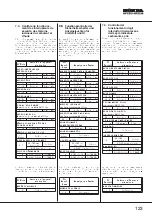
Checking the operation of safety switches and fuel and oil indicator
lights
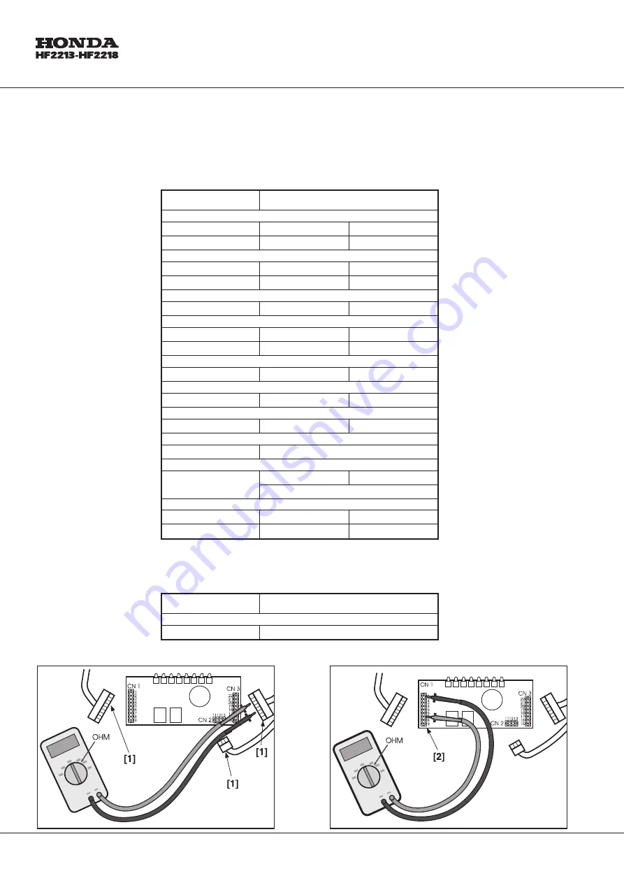
This set is carried out by disconnecting connectors CN 1 - CN 2 - CN 3 and using the Ohmmeter function of the
setting apparatus. This operation must be carried out when the operator is not at the wheel. Measurements must
be taken on the pins on the wiring female connector [1]. The following results must be obtained:
No Contacts
Tester reading and condition
GRASS-CATCHER ATTACHED
11 - 12
¥
(Free)
O (Pressed)
11 - 13
O (Free)
¥
(Pressed)
SEAT MICROSWITCH
15 - 16
¥
(Free)
O (Pressed)
15 - 17
O (Free)
¥
(Pressed)
BRAKE MICROSWITCH
18 - 19
¥
(Free)
O (Pressed)
BLADE MICROSWITCH
19 - 21
O (Free)
¥
(Pressed)
19 - 20
¥
(Free)
O (Pressed)
IN NEUTRAL SIGNAL (from serial N° 8700001)
9 - 1
¥
(Free)
O (Pressed)
GRASS-CATCHER FULL SIGNAL (from serial N° 8700001)
22 - 1
¥
(Free)
O (Pressed)
FUEL RESERVE WARNING LIGHT
15 - 14
O (Reserve )
¥
(Full)
OIL WARNING LIGHT
10 - Earth
O (Always)
LIGHTS SWITCH
2 - 3
22 (OFF with lamp)
O (ON)
¥
(OFF without lamp)
STARTER UNI
5 - 4
¥
(OFF) O (ON)
O (START)
5 - 3
¥
(OFF) O (ON)
O (START)
The following operation must be carried out by taking measurements on the terminals of the PCB [2]. The following
results must be obtained:
No Contacts
Tester reading and condition
ENGINE STOP
1 - 7
O
(Always)
122

