5.8
REMOVAL OF THE PUMP (Hydrostatic drive models)
The hydrostatic pump is made up of a sealed single unit which
is maintenance free. The pump should only be removed in
order to be replaced or for overhaul at the manufacturer’s
service centre.
NOTE:
When in use (particularly when working extra hard) it
is in the nature of the hydrostatic pump to get up to high
temperatures which can reach 105°C at the hottest points.
This is, however, quite normal and has no adverse effect on
functioning.
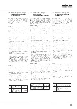
1. Remove the collector channel and disconnect it from the
plate (see 5.3).
2. Remove the cutting deck (see 5.7).
3. Dismantle the screw coupling (see 6.12).
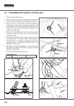
4. Disconnect the two wires from the micro-switch [1],
marking them so that they are not reversed on
re-assembly. Dismantle the articulated joint [2] of the
control rod from the pump lever.
5. Unhook the brake return spring [3] and unscrew the
locknut
[ 4] so that the rod [5] is free to run forwards.
6. Put the lawn-tractor in a vertical position (see chap. 2.4).
7. To remove the pump, undo the two lower screws [6] fixing
on the support [8], and the two upper screws [7] which
attach the pump to the frame. Hold up the pump so that it
does not fall.
NOTE:
On re-assembly, take particular care with the two
self-tapping upper screws [7] which, if not screwed in
correctly, could damage the threads inside the pump, with
the risk of not being able to attach it properly.
8. Carry out the above operations in reverse order.
9. Adjust the brake (see 4.9) and, if the control rod has been
completely dismantled or replaced.
10. Adjust the travel and the “neutral” position of the pedal
(see
4.11).
Tightening torque
[6]
Support fixing screws
30 ¸ 35 Nm
[7]
Pump fixing self-tapping screws
30 ¸ 35 Nm
82

