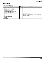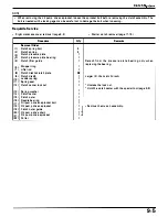
Requisite Service
•
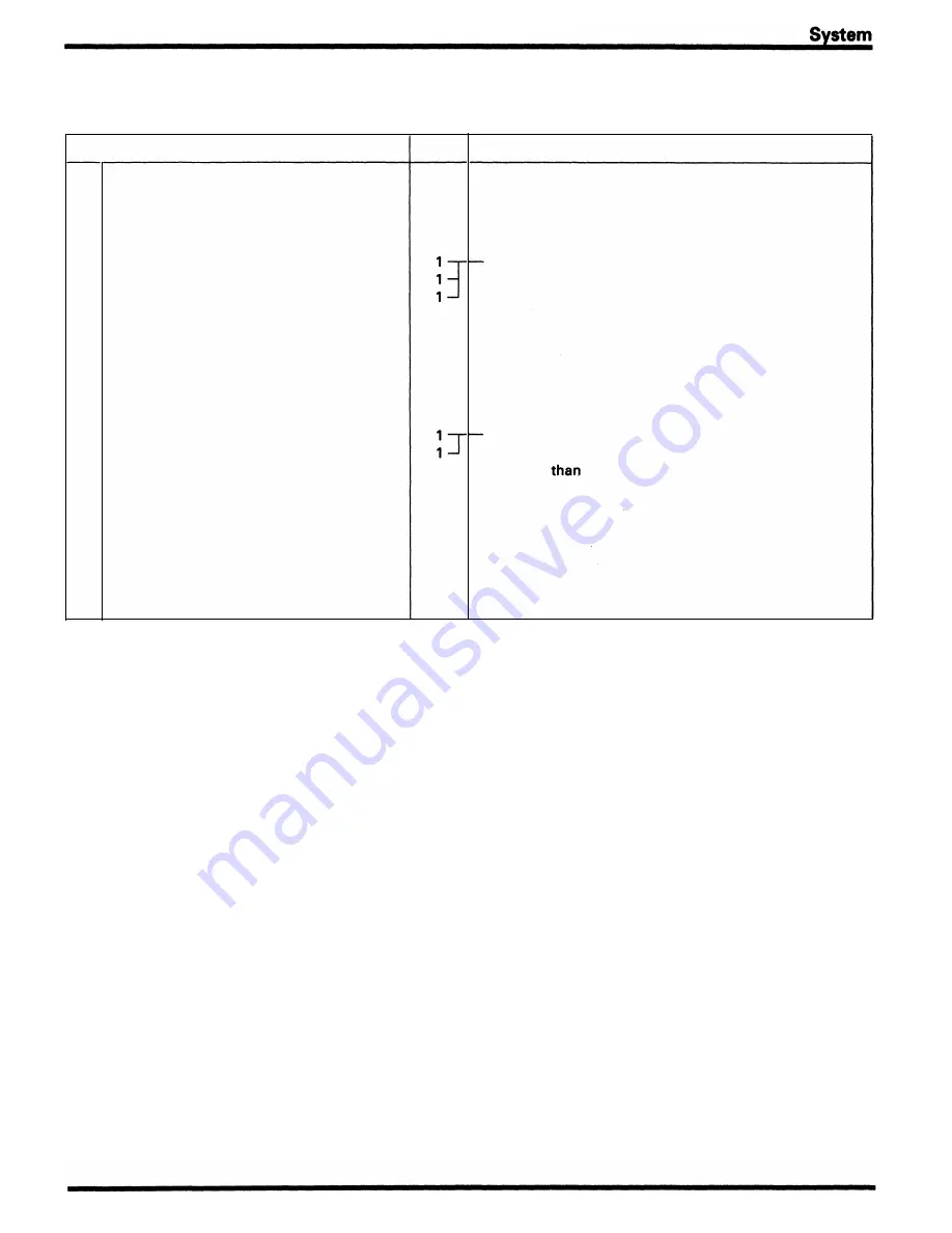
Starter clutch instal lation ( page
1 7- 1 0)
Procedure
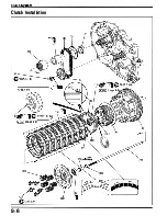
Installation Order
( 1 ) Collar
(2)
Clutch outer guide
(3)
Oil pump d rive sprocket
(4)
Oil pump d rive chain
(5)
Oil pump driven sprocket
(6)
Oil pum p d riven sprocket bolt
(7)
Needle bearing
(8)
Clutch outer
(9)
Clutch center
( 1 0)
Spring washer
( 1 1 )
Clutch center lock n ut
( 1 2)
Spring seat
( 1 3)
J udder spring
( 1 4)
Clutch disc
B
( 1 5)
Clutch disc A/cl utch plate
( 1 6)
Lifter rod
( 1 7 )
Stoppen ring
( 1 8)
Clutch l ifter guide
( 1 9)
Pressu re plate bearing
(20)
Pressu re plate
(2 1 )
Clutch spring
(22)
Clutch spring bolt
Q'ty
1
1
1
1
1
1
1
1
1
8/8
1
1
1
1
1
5
5
Clutch
•
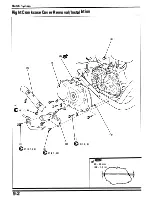
Right crankcase cover installation ( page
9-2)
Remarks
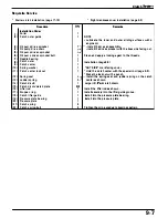
NOTE
•
Lubricate the i n ner and outer sliding su rfaces with
a
engine oil.
•
Insta l l them as an assembly.
•
Install the drive sprocket with the boss side facing out.
Clean and apply a locking agent to the threads.
Installation (page
9-8).
"OUT SIDE" mark facing cover.
•
Hold the clutch center with the special tool ( page
9-8).
•
Stake the lock nut with a punch.
Install the spring seat and judder spring on the clutch
center as shown.
Larger I. D.
clutch disc
A.
Install the lifter rod as shown.
Install securely into the lifter guide groove.
Install into the pressure plate bearing.
Install into the pressure plate.
Tighten them in a gradual, crisscross pattern.
9-7
Summary of Contents for Magna VF750C
Page 1: ...1994 2003 MAGNA VF750C CD HONDA MOTOR CO LTD 1994 ...
Page 2: ......
Page 7: ...MEMO ...
Page 47: ...MEMO ...
Page 65: ...Fuel System Carburetor Removal Installation 5 4 ...
Page 67: ...Fuel System Carburetor Separation 1 5 26 5 6 ...
Page 69: ...Fuel System Carburetor DisassemblyIAssembly 23 1 2 1 5 1 4 0 ring gasket 5 8 ...
Page 71: ...Fuel System Carburetor Combination 27 D D No 1 CARBURETOR 25 0 RING COTIER PIN 5 5 1 0 ...
Page 81: ...Cooling System System Flow Pattern 1 SIPHON TUBE 5 THERMOSTAT 2 RESERVE TANK 3 WATE PUMP 6 2 ...
Page 87: ...MEMO ...
Page 109: ...MEMO ...
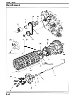
Page 113: ...Clutch System Clutch Removal 9 4 3 1 3 1 2 1 0 l a TooL I page 9 9 8 7 ...
Page 115: ...Clutch System Clutch Installation 1 0 0 9 6 ...
Page 121: ...Gearshift Linkage Gearshift Linkage Removal Installation 8 SHIFTER PLATE ASSEMBLY 1 1 0 4 ...
Page 123: ...MEMO ...
Page 125: ...Crankshaft Piston Transmission Crankcase Separation 6 5 1 1 2 ...
Page 131: ...Crankshaft Piston Transmission Transmission Removal Installation 1 1 1 8 ...
Page 143: ...MEMO ...
Page 145: ...Front Wheel Suspension Steering Handlebar Removal Installation 1 c2 3 2 3 1 7 1 1 0 1 5 1 2 2 ...
Page 189: ...MEMO ...
Page 223: ...MEMO ...
Page 227: ...MEMO ...
Page 243: ...Appendix A Part Numbers 23 10 Carburetor Assembly ...
Page 283: ...Appendix A Part Numbers 23 50 Speedometer Tachometer ...
Page 297: ...MEMO ...
Page 305: ... 1 ...


