General Information
Unit: mm (in)
Lubrication
Item
Engine oil capacity at draining
at disassembly
at oil filter change
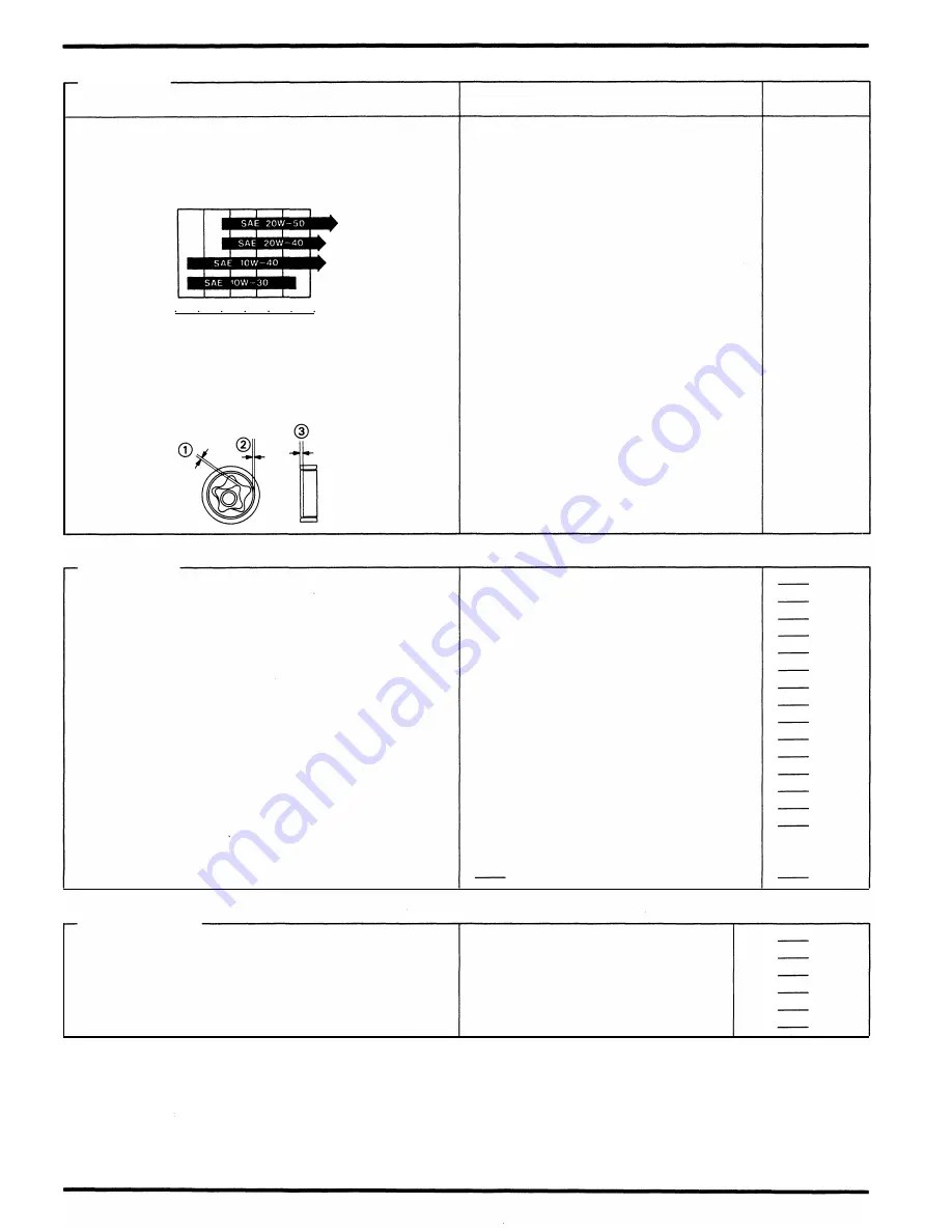
Recommended engine oil
OIL VISCOSITIES
o
zo
40
eo
eo
tOO •F
-20 -oo
o
10
20
:so
40 'C
Oil pressure at oil pressure switch
Oil pump rotor tip clearance
G)
body clearance
®
end clearance
@
Standard
Service Limit
3. 0
lit
( 3. 2
US qt,
2. 6
Imp qt)
--
3.8
lit
(4. 0
US qt,
3 , 3
Imp qt)
--
3. 1
lit
( 3. 3
US qt,
2. 7
Imp qt)
--
Use Honda GN4 4-stroke Oil or equivalent
API Service Classification: SF or SG
Viscosity: SAE
1 0W - 40
Other viscosities shown in the chart may
be used when the average temperature in
your riding area is within the indicated
range.
490 - 588
kPa
( 5 - 6
kg/cm2,
7 1 . 1 - 8 5 . 3
psi) at
6,000
rpm
(80°C/ 1 76°F)
0. 1 0 (0. 004)
0. 1 5 - 0. 22 (0. 00 6 - 0. 009)
0. 02 - 0. 09 (0.001 - 0. 004)
0. 1 5 (0.006)
0. 3 5 (0. 0 1 4)
0. 1 0 (0. 005)
FueiSystem
Carburetor identification number
(49
states type)
(California type)
(Canadian type)
Main jet
Slow jet
Pilot screw initial opening
Pilot screw high altitude adjustment
Float level
Carburetor vacuum difference
Base carburetor (For carburetor synchronization)
Idle speed
(49
states type)
(California type)
(Canadian type)
Throttle grip free play
Pulse secondary air (PAIR) injection system
(California type)
Pulse secondary air inje'ction control valve vacuum
pressure
VP31A
VP30A
VP32D
# 1 02
# 40
see page
5- 1 6
see page
5- 1 7
1 3. 7 (0. 54)
Within
20
mmHg
(0. 8
inHg)
No.
1
carburetor
1 ,000
±
1 00
rpm
1 , 1 00
±
1 00
rpm
1 , 000
±
1 00
rpm
2 - 6 ( 1 /8 - 1 /4)
PAIR check valves are buit in to the PAIR
control valve
Cooling System
Cooling capacity (Radiator and engine)
(Reserve tank)
Radiator cap relief pressure
Thermostat begins to open
Thermostat fully open
Thermostat valve lift
1-6
2. 4
i
(0. 6
US gal,
0. 5
Imp gal)
0.4
i
(0. 1
US gal,
0.09
Imp gal)
1 07.9
kPa
( 1 . 1
kg/cm2,
1 5. 64
psi)
80 - 84°C ( 1 76 - 1 83°F)
95°C ( 203°Fl
8. 0 (0. 3 1 5)
min.
Summary of Contents for Magna VF750C
Page 1: ...1994 2003 MAGNA VF750C CD HONDA MOTOR CO LTD 1994 ...
Page 2: ......
Page 7: ...MEMO ...
Page 47: ...MEMO ...
Page 65: ...Fuel System Carburetor Removal Installation 5 4 ...
Page 67: ...Fuel System Carburetor Separation 1 5 26 5 6 ...
Page 69: ...Fuel System Carburetor DisassemblyIAssembly 23 1 2 1 5 1 4 0 ring gasket 5 8 ...
Page 71: ...Fuel System Carburetor Combination 27 D D No 1 CARBURETOR 25 0 RING COTIER PIN 5 5 1 0 ...
Page 81: ...Cooling System System Flow Pattern 1 SIPHON TUBE 5 THERMOSTAT 2 RESERVE TANK 3 WATE PUMP 6 2 ...
Page 87: ...MEMO ...
Page 109: ...MEMO ...
Page 113: ...Clutch System Clutch Removal 9 4 3 1 3 1 2 1 0 l a TooL I page 9 9 8 7 ...
Page 115: ...Clutch System Clutch Installation 1 0 0 9 6 ...
Page 121: ...Gearshift Linkage Gearshift Linkage Removal Installation 8 SHIFTER PLATE ASSEMBLY 1 1 0 4 ...
Page 123: ...MEMO ...
Page 125: ...Crankshaft Piston Transmission Crankcase Separation 6 5 1 1 2 ...
Page 131: ...Crankshaft Piston Transmission Transmission Removal Installation 1 1 1 8 ...
Page 143: ...MEMO ...
Page 145: ...Front Wheel Suspension Steering Handlebar Removal Installation 1 c2 3 2 3 1 7 1 1 0 1 5 1 2 2 ...
Page 189: ...MEMO ...
Page 223: ...MEMO ...
Page 227: ...MEMO ...
Page 243: ...Appendix A Part Numbers 23 10 Carburetor Assembly ...
Page 283: ...Appendix A Part Numbers 23 50 Speedometer Tachometer ...
Page 297: ...MEMO ...
Page 305: ... 1 ...


