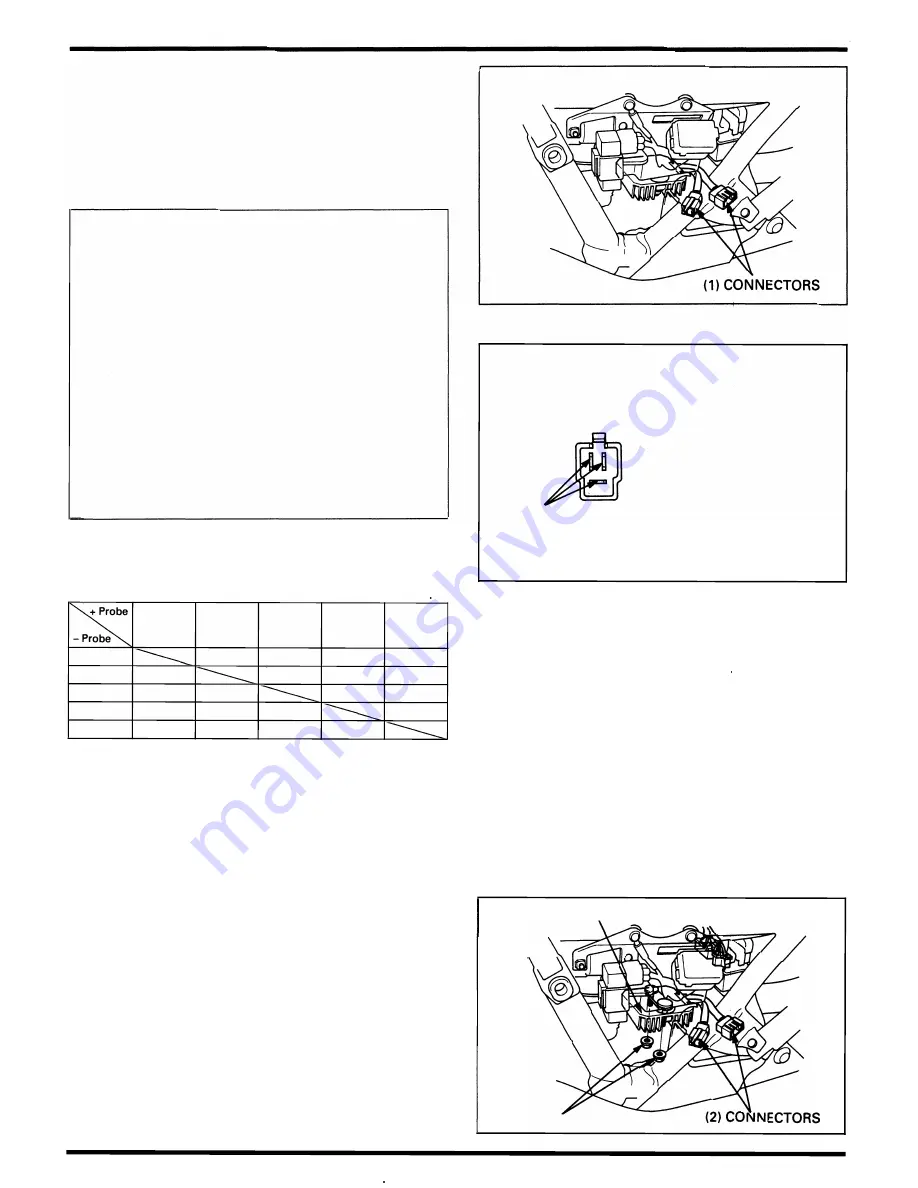
Charging System/ Alternator
Unit Inspection
Provided the ci rcuit on the wi re ha rness side is normal and
there are no loose connections at the connectors, inspect
the reg u l ator/rectifi e r u n it by measuring the resista nce
between the term inals.
NOTE
•
You'l l get false readings if the probes touch you fi n
gers.
•
U se the specified m u ltimeters. U s i n g oth e r eq u i p
ment may not allow you to obtai n the correct resu lts.
This is due to the characteristic of sem iconductors,
w h i c h h a ve d i ffe r e n t va l u e s d e p e n d i n g o n t h e
applied voltage.
Specific Multimeter:
-
0741 1
-
0020000 (KOWA Digital type)
- 07308 - 0020001 (SANWA Analogue type)
•
Select the fol l owing range:
SANWA:
x
kO
KOWA:
x
1 00
•
Using a n o l d battery stored i n the m u lti m ete r can
cause inaccu rate readi ngs. Check the battery if the
m u ltimeter resistance is i ncorrect.
•
When using the KOWA m u ltimeter, remember that
a l l readings should be m u ltipl ied by 1 00.
Replace the reg u lator/rectifier u n it if the resistance value
between the terminals is abnorm a l .
Unit· 0
Red/White
Yellow
Yellow
Yellow
Green
Red/White
�
�
�
�
Yellow
500 - 10k
�
�
�
Yellow
500 - 1 0k
�
�
�
Yellow
500 - 10k
�
�
�
Green
700 - 1 5k 500 - 1 0k 500 - 10k 500 - 10k
Removal/Installation
Disconnect the regu lator/rectifier connectors.
Remove the mounting n uts and regu l ator/rectifier u n it.
Instal l ation is i n the reverse order of remova l .
1 5-8
( 1 ) YELLOW
p
(2) G R E E N
(3) RED/WHITE
( 1 ) REG U LATOR/RECTIFIER
(3) N UTS
Summary of Contents for Magna VF750C
Page 1: ...1994 2003 MAGNA VF750C CD HONDA MOTOR CO LTD 1994 ...
Page 2: ......
Page 7: ...MEMO ...
Page 47: ...MEMO ...
Page 65: ...Fuel System Carburetor Removal Installation 5 4 ...
Page 67: ...Fuel System Carburetor Separation 1 5 26 5 6 ...
Page 69: ...Fuel System Carburetor DisassemblyIAssembly 23 1 2 1 5 1 4 0 ring gasket 5 8 ...
Page 71: ...Fuel System Carburetor Combination 27 D D No 1 CARBURETOR 25 0 RING COTIER PIN 5 5 1 0 ...
Page 81: ...Cooling System System Flow Pattern 1 SIPHON TUBE 5 THERMOSTAT 2 RESERVE TANK 3 WATE PUMP 6 2 ...
Page 87: ...MEMO ...
Page 109: ...MEMO ...
Page 113: ...Clutch System Clutch Removal 9 4 3 1 3 1 2 1 0 l a TooL I page 9 9 8 7 ...
Page 115: ...Clutch System Clutch Installation 1 0 0 9 6 ...
Page 121: ...Gearshift Linkage Gearshift Linkage Removal Installation 8 SHIFTER PLATE ASSEMBLY 1 1 0 4 ...
Page 123: ...MEMO ...
Page 125: ...Crankshaft Piston Transmission Crankcase Separation 6 5 1 1 2 ...
Page 131: ...Crankshaft Piston Transmission Transmission Removal Installation 1 1 1 8 ...
Page 143: ...MEMO ...
Page 145: ...Front Wheel Suspension Steering Handlebar Removal Installation 1 c2 3 2 3 1 7 1 1 0 1 5 1 2 2 ...
Page 189: ...MEMO ...
Page 223: ...MEMO ...
Page 227: ...MEMO ...
Page 243: ...Appendix A Part Numbers 23 10 Carburetor Assembly ...
Page 283: ...Appendix A Part Numbers 23 50 Speedometer Tachometer ...
Page 297: ...MEMO ...
Page 305: ... 1 ...


