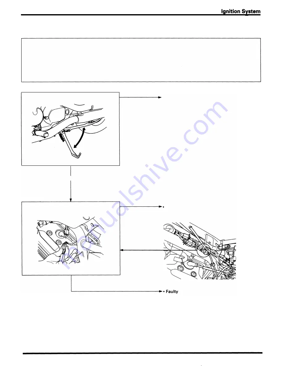
Engine Starts, But Side Stand Switch Does Not Function
NOTE
The side stand switch should fu nction as follows:
•
When the transm ission is sh ifted i nto a gear from neutral with the side stand down, the ignition shuts off and the
engine stops.
•
When i n neutral, the neutra l switch line (a ) of the ignition control module (ICM) is connected to g round via the side
stand switch.
When the side stand is up, the side stand switch line (b) of the ignition control module (ICM) passes to g round via
the side stand switch. The ignition control module (ICM) monitors l ines (a) and (b), and provides spark only when
one or both of those l i nes is connected to ground via the neutral switch or the side stand switch.
Check the side stand indicator fu nction.
Normal
•
Open ci rcuit i n G reen/White wire
Abnormal
Normal
Check for contin u ity between each terminal of
Loose or poor contact of related connectors
side stan d switch as follows.
•
Open ci rcuit in G reen/White wire
Side stand up: Green/White - Green
Side stand down: Yellow/Black - Green
•
Bu rnt indicator b u l b
Abnormal
side stand switch
1 6-7
Summary of Contents for Magna VF750C
Page 1: ...1994 2003 MAGNA VF750C CD HONDA MOTOR CO LTD 1994 ...
Page 2: ......
Page 7: ...MEMO ...
Page 47: ...MEMO ...
Page 65: ...Fuel System Carburetor Removal Installation 5 4 ...
Page 67: ...Fuel System Carburetor Separation 1 5 26 5 6 ...
Page 69: ...Fuel System Carburetor DisassemblyIAssembly 23 1 2 1 5 1 4 0 ring gasket 5 8 ...
Page 71: ...Fuel System Carburetor Combination 27 D D No 1 CARBURETOR 25 0 RING COTIER PIN 5 5 1 0 ...
Page 81: ...Cooling System System Flow Pattern 1 SIPHON TUBE 5 THERMOSTAT 2 RESERVE TANK 3 WATE PUMP 6 2 ...
Page 87: ...MEMO ...
Page 109: ...MEMO ...
Page 113: ...Clutch System Clutch Removal 9 4 3 1 3 1 2 1 0 l a TooL I page 9 9 8 7 ...
Page 115: ...Clutch System Clutch Installation 1 0 0 9 6 ...
Page 121: ...Gearshift Linkage Gearshift Linkage Removal Installation 8 SHIFTER PLATE ASSEMBLY 1 1 0 4 ...
Page 123: ...MEMO ...
Page 125: ...Crankshaft Piston Transmission Crankcase Separation 6 5 1 1 2 ...
Page 131: ...Crankshaft Piston Transmission Transmission Removal Installation 1 1 1 8 ...
Page 143: ...MEMO ...
Page 145: ...Front Wheel Suspension Steering Handlebar Removal Installation 1 c2 3 2 3 1 7 1 1 0 1 5 1 2 2 ...
Page 189: ...MEMO ...
Page 223: ...MEMO ...
Page 227: ...MEMO ...
Page 243: ...Appendix A Part Numbers 23 10 Carburetor Assembly ...
Page 283: ...Appendix A Part Numbers 23 50 Speedometer Tachometer ...
Page 297: ...MEMO ...
Page 305: ... 1 ...


