Maintenance
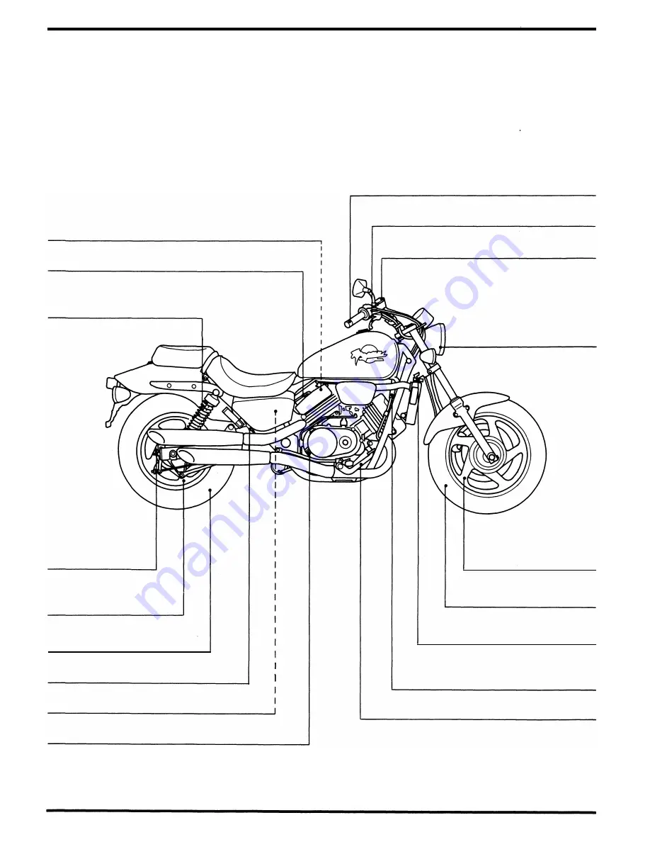
Service Access Guide
•
The following shows the locations of the parts that must be removed for the maintenance items listed below.
Refer to the Common Service Manual for items not included in this manual .
•
Refer to section 2 (Frame/Body Panels/Exhaust System) . for the parts that m ust be removed for service.
For example: Air Cleaner (Contamination, clogging, replacement) : Parts
•
Rear Fairing -The part required to be removed for service .
( 1 8) Valve Clearance ( Inspection/Adjustment : page 3-5)
•
Fuel tank
( 1 7) Spark Plug (Wear, damage, color)
( 1 6) Suspension
(Loose, wear, damage)
( 1 5) Brake Drum
(Shoe wear)
( 1 4) Wheel
( Damage, runout,
corrosion)
( 1 3) Tire
(Wear, damage, air pressure)
( 1 2) Brake Light Switch (Operation)
( 1 1 ) Reserve Coolant Tank Cap
( 1 0) Oil Level Gauge (Oil level check, replacement)
3-2
( 1 ) Throttle Grip (Operation, free play)
(2) Brake Lever (Air in system )
(3) Master Cylinder
( Level check, fluid replacement)
(4) Headlight (Ai m : page 3- 1 0)
(6) Tire
( 5 ) Wheel
( Damage, runout,
corrosion)
(Wear, damage, air pressure)
( 7) Radiator Cap
( Coolant replacement)
(8) Pulse Secondary Air I njection System
(California type only; Air leaks,
deterioration, damage)
·
(9) Brake Pedal ( Free play, height)
Summary of Contents for Magna VF750C
Page 1: ...1994 2003 MAGNA VF750C CD HONDA MOTOR CO LTD 1994 ...
Page 2: ......
Page 7: ...MEMO ...
Page 47: ...MEMO ...
Page 65: ...Fuel System Carburetor Removal Installation 5 4 ...
Page 67: ...Fuel System Carburetor Separation 1 5 26 5 6 ...
Page 69: ...Fuel System Carburetor DisassemblyIAssembly 23 1 2 1 5 1 4 0 ring gasket 5 8 ...
Page 71: ...Fuel System Carburetor Combination 27 D D No 1 CARBURETOR 25 0 RING COTIER PIN 5 5 1 0 ...
Page 81: ...Cooling System System Flow Pattern 1 SIPHON TUBE 5 THERMOSTAT 2 RESERVE TANK 3 WATE PUMP 6 2 ...
Page 87: ...MEMO ...
Page 109: ...MEMO ...
Page 113: ...Clutch System Clutch Removal 9 4 3 1 3 1 2 1 0 l a TooL I page 9 9 8 7 ...
Page 115: ...Clutch System Clutch Installation 1 0 0 9 6 ...
Page 121: ...Gearshift Linkage Gearshift Linkage Removal Installation 8 SHIFTER PLATE ASSEMBLY 1 1 0 4 ...
Page 123: ...MEMO ...
Page 125: ...Crankshaft Piston Transmission Crankcase Separation 6 5 1 1 2 ...
Page 131: ...Crankshaft Piston Transmission Transmission Removal Installation 1 1 1 8 ...
Page 143: ...MEMO ...
Page 145: ...Front Wheel Suspension Steering Handlebar Removal Installation 1 c2 3 2 3 1 7 1 1 0 1 5 1 2 2 ...
Page 189: ...MEMO ...
Page 223: ...MEMO ...
Page 227: ...MEMO ...
Page 243: ...Appendix A Part Numbers 23 10 Carburetor Assembly ...
Page 283: ...Appendix A Part Numbers 23 50 Speedometer Tachometer ...
Page 297: ...MEMO ...
Page 305: ... 1 ...


