Head/Valves
NOTE
•
Service the front cyl inder head using the same procedu re as the rea r cyl i nder head.
•
Mark a l l parts d u ring disassem bly so they can be placed back thei r original position.
•
Remove carbon deposits from the combustion cham ber and clean off the head gasket surface, before assem bly.
- Avoid damaging the gasket surface.
- Gaskets wil l come off easier soaked in solvent.
•
Valve g uide replacement see Section 9 of the Com mon Service Manual.
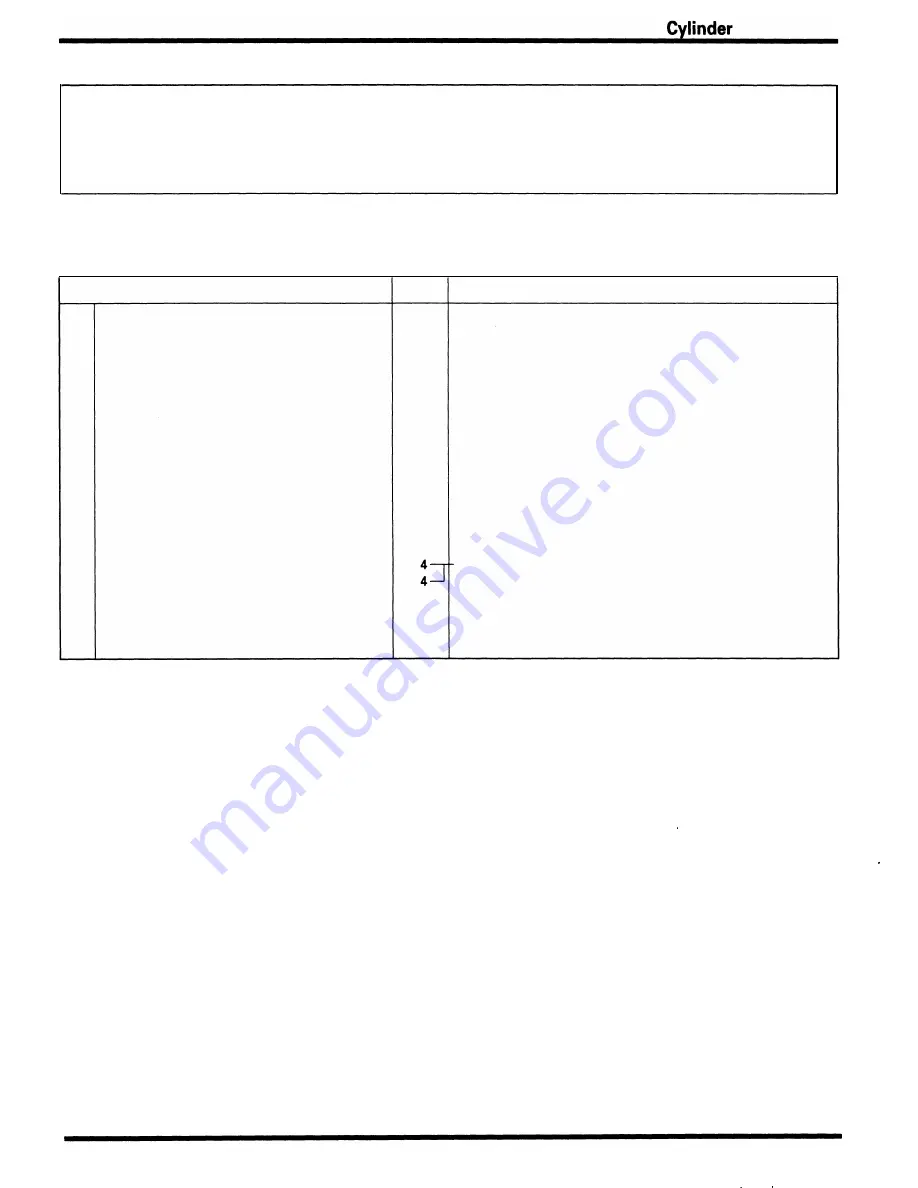
Requisite Service
•
Cylinder head remova l/instal lation (page 8-4)
Procedure
Disassembly Order
( 1 ) Insulator
(2) Valve l ifter
(3) Valve shi m
(4) Valve spring cotter
(5) Valve spring retainer
(6) Valve spring
(7) I ntake valve
(8) Exhaust valve
(9) Stem seal
( 1 0) Valve spring seat
( 1 1 ) Valve guide
Q'ty
Remarks
Assem bly is in the reverse order of d isassembly
2
NOTE
•
Align the groove of the insu lator with the lug of the
cyl inder head.
8
NOTE
•
Remove using a hand lapping tool . Do not damage the
cyli nder head-lifter sliding surface.
8
1 6
NOTE
•
Removal/Insta l lation (page 8- 1 7 )
•
To prevent loss of tension, d o not com press the va lve
spring more than necessa ry.
8
8
At instal lation, i nsta l l the valve springs with the tightly
would coi ls end facing the com bustion cham ber.
NOTE
•
Before instal lation, lubricate each valve stem with
molybdenum disu lfide oil.
8
8
8
Valve guide projection ( page 1 -7 )
8-7
Summary of Contents for Magna VF750C
Page 1: ...1994 2003 MAGNA VF750C CD HONDA MOTOR CO LTD 1994 ...
Page 2: ......
Page 7: ...MEMO ...
Page 47: ...MEMO ...
Page 65: ...Fuel System Carburetor Removal Installation 5 4 ...
Page 67: ...Fuel System Carburetor Separation 1 5 26 5 6 ...
Page 69: ...Fuel System Carburetor DisassemblyIAssembly 23 1 2 1 5 1 4 0 ring gasket 5 8 ...
Page 71: ...Fuel System Carburetor Combination 27 D D No 1 CARBURETOR 25 0 RING COTIER PIN 5 5 1 0 ...
Page 81: ...Cooling System System Flow Pattern 1 SIPHON TUBE 5 THERMOSTAT 2 RESERVE TANK 3 WATE PUMP 6 2 ...
Page 87: ...MEMO ...
Page 109: ...MEMO ...
Page 113: ...Clutch System Clutch Removal 9 4 3 1 3 1 2 1 0 l a TooL I page 9 9 8 7 ...
Page 115: ...Clutch System Clutch Installation 1 0 0 9 6 ...
Page 121: ...Gearshift Linkage Gearshift Linkage Removal Installation 8 SHIFTER PLATE ASSEMBLY 1 1 0 4 ...
Page 123: ...MEMO ...
Page 125: ...Crankshaft Piston Transmission Crankcase Separation 6 5 1 1 2 ...
Page 131: ...Crankshaft Piston Transmission Transmission Removal Installation 1 1 1 8 ...
Page 143: ...MEMO ...
Page 145: ...Front Wheel Suspension Steering Handlebar Removal Installation 1 c2 3 2 3 1 7 1 1 0 1 5 1 2 2 ...
Page 189: ...MEMO ...
Page 223: ...MEMO ...
Page 227: ...MEMO ...
Page 243: ...Appendix A Part Numbers 23 10 Carburetor Assembly ...
Page 283: ...Appendix A Part Numbers 23 50 Speedometer Tachometer ...
Page 297: ...MEMO ...
Page 305: ... 1 ...


