SHOCK ABSORBER
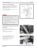
UPPER MOUNTING BOLT/NUT
SHOCK ABSORBER
LOWER MOUNTING BOLT
XL2 0 0
12-12
DISPOSAL OF THE SHOCK ABSORBER
Center punch the damper case to mark the drilling point,
approximately 15 mm (0.59 in) from the top surface. Wrap the
damper unit inside a plastic bag. Support the damper unit
upright in a vise as shown.
Through the open end of the bag, insert a drill motor with a sharp
2-3 mm (5/64 - 1/8 in) drill bit.
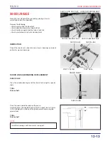
Install the shock absorber lower mounting bolt.
Install the shock link-to-shock arm bolt.
Tighten the mounting nuts to the specified torque.
TORQUE: 45 N.m (4.5 kg.m, 32 ft-lb)
Install the side covers.
REAR WHEEL/SUSPENSION
t
Hold the bag around the drill motor and briefly run the drill motor
inside the bag; this will inflate the bag with air from the motor and
help keep the bag from getting caught in the bit when you start.
INSTALLATION
Install the shock absorber from the bottom.
Install and tighten the upper mounting bolt to the specified
torque.
TORQUE: 45 N.m (4.5 kg.m, 32 ft-lb)
• Do not use a dull drill bit which could cause build-up of
excessive heat and pressure inside the damper, leading to
explosion and severe personal injury.
• The shock absorber contains nitrogen gas and oil under
high pressure. Do not drill any farther down the damper
case than the measurement given above, or you may drill
into the oil chamber; oil escaping under high pressure may
cause serious personal injury.
• Always wear eye protection to avoid getting metal shavings
in your eyes when the gas pressure is released.
The plastic bag is only intended to shield you from the
escaping gas.
PLASTIC BAG
DRILL BIT
SHOCK ABSORBER
Summary of Contents for XL200 2001
Page 1: ...SH O PMANU AL XL200 MOTO HONDA DA AMAZÔNIA LTDA 2001 1 ...
Page 15: ...XL2 0 0 GENERAL INFORMATION 1 11 ...
Page 16: ...XL2 0 0 1 12 GENERAL INFORMATION ...
Page 17: ...XL2 0 0 GENERAL INFORMATION 1 13 ...
Page 18: ...XL2 0 0 1 14 GENERAL INFORMATION ...
Page 19: ...XL2 0 0 GENERAL INFORMATION 1 15 NOTES ...
Page 22: ...XL2 0 0 LUBRICATION 2 0 CRANKSHAFT OIL FILTER ROTOR OIL PUMP COUNTERSHAFT MAIN SHAFT CAMSHAFT ...
Page 29: ...XL2 0 0 2 8 LUBRICATION NOTES ...
Page 48: ...XL2 0 0 FUEL SYSTEM 4 0 ...
Page 64: ...XL2 0 0 FUEL SYSTEM 4 17 NOTES ...
Page 67: ...5 0 XL2 0 0 ENGINE REMOVAL INSTALLATION ...
Page 92: ...XL2 0 0 CYLINDER HEAD VALVES 6 19 NOTAS ...
Page 95: ...XL2 0 0 CYLINDER PISTON 7 0 ...
Page 101: ...XL2 0 0 CYLINDER PISTON 7 7 NOTAS ...
Page 116: ...XL2 0 0 CLUTCH GEARSHIFT LINKAGE 8 13 NOTES ...
Page 119: ...XL2 0 0 ALTERNATOR STARTER CLUTCH 9 0 75 Nm 7 5 kg m 53 ft lb 5 Nm 0 5 kg m 4 ft lb ...
Page 129: ...XL2 0 0 ALTERNATOR STARTER CLUTCH 9 11 NOTAS ...
Page 132: ...XL2 0 0 CRANKSHAFT TRANSMISSION 10 0 12 N m 1 2 kg m 9ft lb ...
Page 144: ...XL2 0 0 CRANKSHAFT TRANSMISSION 10 13 NOTAS ...
Page 169: ...XL2 0 0 FRONT WHEEL SUSPENSION STEERING 11 23 NOTAS ...
Page 172: ...XL2 0 0 REAR WHEEL SUSPENSION 12 0 ...
Page 190: ...XL2 0 0 REAR WHEEL SUSPENSION 12 19 NOTAS ...
Page 226: ...XL2 0 0 IGNITION SYSTEM 16 7 NOTES ...
Page 237: ...XL2 0 0 ELECTRIC STARTER 17 9 NOTES ...
Page 240: ...XL2 0 0 LIGHTS METERS SWITCHES 18 0 ...
Page 248: ...XL2 0 0 LIGHTS METERS SWITCHES 18 9 NOTES ...
Page 250: ...XL2 0 0 19 WIRING DIAGRAM 19 1 19 ...
Page 257: ...MOTO HONDA DA AMAZÔNIA LTDA ...


