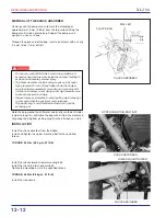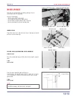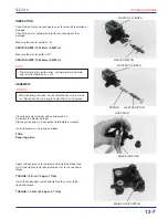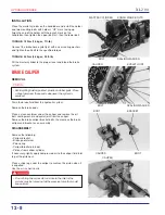
MASTER CYLINDER
BLEED HOSE
BLEED VALVE
BRAKE BLEEDER
BLEED VALVE
XL2 0 0
HYDRAULIC BRAKE
13-3
BRAKE FLUID REPLACEMENT/AIR
BLEEDING
Check the master cylinder parallel to the ground
h
BRAKE FLUID DRAINING
Connect a bleed hose to the bleed valve.
Loosen the caliper bleed valve and pump the brake lever. Stop
operating the brake when fluid stops flowing out of the bleed
valve.
t
BRAKE FLUID FILLING/AIR BLEEDING
h
Fill the master cylinder with DOT4 brake fluid to the upper level.
Connect the Mityvac Brake Bleeder Nº 6860 or equivalent to the
bleed valve.
NOTE
Pump the brake bleeder and loosen the bleed valve.
Add fluid when the fluid level in the master cylinder is low to
prevent drawing air into the system.
Repeat the above procedures until no air bubbles appear in the
plastic hose.
NOTE
• If air is entering the bleeder from around the bleed valve
threads, seal the thread with teflon tape.
• Check the fluid level often while bleeding the brakes to
prevent air from being pumped into the system.
• Do not mix brake fluid types and never reuse the
contaminated fluid which has been pumped out during
brake bleeding, because this will impair the efficiency of the
brake system.
• When using a brake bleeding tool, follow the manufacturer’s
operating instruction.
• Do not mix different types of fluid since they are not compatible.
• A contaminated brake disc or pad reduces stopping power.
Discard contaminated pads and clean the contaminated disc
with a high quality brake degreasing agent.
• Avoid spilling fluid on painted, plastic or rubber parts. Place
a shop towel over these parts whenever the system is
serviced.
Summary of Contents for XL200 2001
Page 1: ...SH O PMANU AL XL200 MOTO HONDA DA AMAZÔNIA LTDA 2001 1 ...
Page 15: ...XL2 0 0 GENERAL INFORMATION 1 11 ...
Page 16: ...XL2 0 0 1 12 GENERAL INFORMATION ...
Page 17: ...XL2 0 0 GENERAL INFORMATION 1 13 ...
Page 18: ...XL2 0 0 1 14 GENERAL INFORMATION ...
Page 19: ...XL2 0 0 GENERAL INFORMATION 1 15 NOTES ...
Page 22: ...XL2 0 0 LUBRICATION 2 0 CRANKSHAFT OIL FILTER ROTOR OIL PUMP COUNTERSHAFT MAIN SHAFT CAMSHAFT ...
Page 29: ...XL2 0 0 2 8 LUBRICATION NOTES ...
Page 48: ...XL2 0 0 FUEL SYSTEM 4 0 ...
Page 64: ...XL2 0 0 FUEL SYSTEM 4 17 NOTES ...
Page 67: ...5 0 XL2 0 0 ENGINE REMOVAL INSTALLATION ...
Page 92: ...XL2 0 0 CYLINDER HEAD VALVES 6 19 NOTAS ...
Page 95: ...XL2 0 0 CYLINDER PISTON 7 0 ...
Page 101: ...XL2 0 0 CYLINDER PISTON 7 7 NOTAS ...
Page 116: ...XL2 0 0 CLUTCH GEARSHIFT LINKAGE 8 13 NOTES ...
Page 119: ...XL2 0 0 ALTERNATOR STARTER CLUTCH 9 0 75 Nm 7 5 kg m 53 ft lb 5 Nm 0 5 kg m 4 ft lb ...
Page 129: ...XL2 0 0 ALTERNATOR STARTER CLUTCH 9 11 NOTAS ...
Page 132: ...XL2 0 0 CRANKSHAFT TRANSMISSION 10 0 12 N m 1 2 kg m 9ft lb ...
Page 144: ...XL2 0 0 CRANKSHAFT TRANSMISSION 10 13 NOTAS ...
Page 169: ...XL2 0 0 FRONT WHEEL SUSPENSION STEERING 11 23 NOTAS ...
Page 172: ...XL2 0 0 REAR WHEEL SUSPENSION 12 0 ...
Page 190: ...XL2 0 0 REAR WHEEL SUSPENSION 12 19 NOTAS ...
Page 226: ...XL2 0 0 IGNITION SYSTEM 16 7 NOTES ...
Page 237: ...XL2 0 0 ELECTRIC STARTER 17 9 NOTES ...
Page 240: ...XL2 0 0 LIGHTS METERS SWITCHES 18 0 ...
Page 248: ...XL2 0 0 LIGHTS METERS SWITCHES 18 9 NOTES ...
Page 250: ...XL2 0 0 19 WIRING DIAGRAM 19 1 19 ...
Page 257: ...MOTO HONDA DA AMAZÔNIA LTDA ...


