RUBBER COVER
LOCK NUT
ADJUSTER
CASE COVER
SCREW/WASHER
XL2 0 0
MAINTENANCE
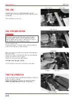
Throttle grip free play can be adjusted using the adjuster at the
handlebar.
Slide the rubber cover off the lower mount and loosen the lock
nut.
Turn the adjuster to obtain 2-6 mm (1/16 - 1/4 in) of free play.
Then tighten the lock nut and slide the rubber cover back.
Replace the throttle cable with a new one if the adjuster or cable
is damaged.
Check that the throttle grip moves smoothly and returns
completely.
3-5
CARBURETOR CHOKE
Check the smooth choke operation.
Adjust the choke lever freeplay, by loosening the cable clamp
screw and move the cable outer casing.
After adjustment tighten the clamp screw securely.
AIR CLEANER
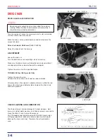
Remove the left side cover.
Remove the following:
– four screws
– four washers
– air cleaner case cover
– element setting nut
– air cleaner element
Inspect and clean the element according to the Maintenance
Schedule.
Wash the element away any accumulated dust or dirt, by gently
squeezing it in non-flammable or high flush point solvent.
t
h
Install the element in the reverse order of removal.
Cleaning the element with gasoline or any acid, alkaline, or
organic, volatile type oil may cause improper ignition,
deterioration of the element, or a loosening of the element
adhesive.
Spread clean #80-90 gear oil on the element, rubbing in
thoroughly over the surface with both hands, and then
squeeze out any excess oil.
Using gasoline or low flash point solvent for cleaning parts
may result in a fire or explosion.
SQUEEZE OUT
SOLVENT
THOROUGHLY
SQUEEZE OUT
EXCESS OIL
GEAR OIL
(SAE# 80-90)
WASH IN
SOLVENT
Summary of Contents for XL200 2001
Page 1: ...SH O PMANU AL XL200 MOTO HONDA DA AMAZÔNIA LTDA 2001 1 ...
Page 15: ...XL2 0 0 GENERAL INFORMATION 1 11 ...
Page 16: ...XL2 0 0 1 12 GENERAL INFORMATION ...
Page 17: ...XL2 0 0 GENERAL INFORMATION 1 13 ...
Page 18: ...XL2 0 0 1 14 GENERAL INFORMATION ...
Page 19: ...XL2 0 0 GENERAL INFORMATION 1 15 NOTES ...
Page 22: ...XL2 0 0 LUBRICATION 2 0 CRANKSHAFT OIL FILTER ROTOR OIL PUMP COUNTERSHAFT MAIN SHAFT CAMSHAFT ...
Page 29: ...XL2 0 0 2 8 LUBRICATION NOTES ...
Page 48: ...XL2 0 0 FUEL SYSTEM 4 0 ...
Page 64: ...XL2 0 0 FUEL SYSTEM 4 17 NOTES ...
Page 67: ...5 0 XL2 0 0 ENGINE REMOVAL INSTALLATION ...
Page 92: ...XL2 0 0 CYLINDER HEAD VALVES 6 19 NOTAS ...
Page 95: ...XL2 0 0 CYLINDER PISTON 7 0 ...
Page 101: ...XL2 0 0 CYLINDER PISTON 7 7 NOTAS ...
Page 116: ...XL2 0 0 CLUTCH GEARSHIFT LINKAGE 8 13 NOTES ...
Page 119: ...XL2 0 0 ALTERNATOR STARTER CLUTCH 9 0 75 Nm 7 5 kg m 53 ft lb 5 Nm 0 5 kg m 4 ft lb ...
Page 129: ...XL2 0 0 ALTERNATOR STARTER CLUTCH 9 11 NOTAS ...
Page 132: ...XL2 0 0 CRANKSHAFT TRANSMISSION 10 0 12 N m 1 2 kg m 9ft lb ...
Page 144: ...XL2 0 0 CRANKSHAFT TRANSMISSION 10 13 NOTAS ...
Page 169: ...XL2 0 0 FRONT WHEEL SUSPENSION STEERING 11 23 NOTAS ...
Page 172: ...XL2 0 0 REAR WHEEL SUSPENSION 12 0 ...
Page 190: ...XL2 0 0 REAR WHEEL SUSPENSION 12 19 NOTAS ...
Page 226: ...XL2 0 0 IGNITION SYSTEM 16 7 NOTES ...
Page 237: ...XL2 0 0 ELECTRIC STARTER 17 9 NOTES ...
Page 240: ...XL2 0 0 LIGHTS METERS SWITCHES 18 0 ...
Page 248: ...XL2 0 0 LIGHTS METERS SWITCHES 18 9 NOTES ...
Page 250: ...XL2 0 0 19 WIRING DIAGRAM 19 1 19 ...
Page 257: ...MOTO HONDA DA AMAZÔNIA LTDA ...


