background image

Revision 1.3

P/N: 95107

FLEX Header 

Operator Manual

2020

®

SDX Series

Summary of Contents for AirFLEX SDX 225

Page 1: ...Revision 1 3 P N 95107 FLEX Header Operator Manual 2020 SDX Series...

Page 2: ......

Page 3: ...ered on the header page 51 ___Set Auto Header Height parameters in combine control panel Combine and Sensitivity Settings ___Calibrate combine In FLEX mode ___Run header and fine tune drive belt to mi...

Page 4: ...lt info pg 43 updated combine feeder house speed pg 46 Updated automatix info indicator arrows etc updated skid shoe extension info pg 53 updated hyd tilt cyl throughout document updated manual tilt c...

Page 5: ...anufacturing Ltd SDX Header Page 5 P N 95107 2 Copyright Information Original Instructions 2020 Honey Bee Manufacturing Ltd All Rights Reserved Patents https www honeybee ca patents php all other pate...

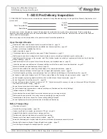
Page 6: ...Page 6 Honey Bee Manufacturing Ltd SDX Header P N 95107...

Page 7: ...Safety 23 7 15 Keep Equipment Clean 23 8 Specifications 25 8 1 Dimensions Specifications 25 9 Safety Decal Locations 27 10 Equipment Overview 32 10 1 Optional Transport Package 32 10 2 Automatic Head...

Page 8: ...9 14 Header Setup 50 14 1 Reel Setup 50 14 1 1 Reel Finger Timing Adjustment 50 14 1 2 Reel Height Adjustment bottom limit based on finger timing 50 14 1 3 Reel Centering 51 14 2 Feed Auger Finger Tim...

Page 9: ...ight Switch 70 17 3 Touch Screen Buttons 70 17 3 1 Adjust Screen Brightness 70 17 3 2 Settings 70 17 4 Settings Screen 70 17 5 Sensor Bar Graphs 71 17 6 Warnings 71 17 6 1 Air Pressure Warnings 71 17...

Page 10: ...Center Draper Belt 96 20 7 7 Draper Splicing 97 20 8 Reel 98 20 8 1 Set Reel Safety Stops 98 20 8 2 Rephasing Reel Cylinders 98 20 8 3 Automatic Reel Speed 98 20 8 4 Reel Speed Sensor Adjustment 98 20...

Page 11: ...Alternative and Synthetic Lubricants 120 20 19 5 Feeder Deck Drive Chain Lubrication 120 20 19 6 Knife Head Lubrication 120 20 19 7 Grease Specifications 120 20 19 8 Wheel Bearing Grease 121 20 19 9...

Page 12: ...matix Lite Display Sensor Identification 139 22 5 Reel Speed Sensor Location 140 22 6 Lift Valve Performance BeeBox 141 22 7 2016 or later JD Combine Check valve Kit 142 22 8 Recommended Torque Values...

Page 13: ...sible for any paint deterioration resulting from salt or harsh chemical corrosion if this equipment is not properly washed after transport Use a mild soap solution then rinse thoroughly If this equipm...

Page 14: ...Page 14 Honey Bee Manufacturing Ltd SDX Header P N 95107...

Page 15: ...Number Delivery Date Modification Record Date Modification Honey Bee Manufacturing Limited is continually striving to improve its products We reserve the right to make improvements or changes when it...

Page 16: ...Page 16 Honey Bee Manufacturing Ltd SDX Header P N 95107...

Page 17: ...ber plate is located directly on top of the hydraulic bulkhead as shown below The letters and numbers stamped on the plate identify the header Please have this serial number on hand when ordering repl...

Page 18: ...Page 18 Honey Bee Manufacturing Ltd SDX Header P N 95107...

Page 19: ...nship under normal use and service Obligations under this warranty shall extend for a period of 1 year 12 months following the date of first use to the original purchaser and shall be limited to at th...

Page 20: ...Page 20 Honey Bee Manufacturing Ltd SDX Header P N 95107...

Page 21: ...proper procedures are not followed Notifies you of important information to which you should pay attention 7 3 Read and Understand Instructions and Warnings Please read and understand all warnings and...

Page 22: ...grene may result Doctors unfamiliar with this type of injury should reference a knowledgeable medical source 7 10 Transporting the Header When transporting the header frequently check for traffic from...

Page 23: ...position hydraulically supported devices can settle or drop suddenly Do not support the header on cinder blocks hollow tiles or props that may crumble under continuous load Do not work under a header...

Page 24: ...Page 24 Honey Bee Manufacturing Ltd SDX Header P N 95107...

Page 25: ...0 lb 3591 kg 8668 lbs 3940 kg 9056 lbs 4116 kg 9444 lbs 4293 kg Optional Transport Package 785 lbs 356 kg Cutting System Mechanically driven knife drive with SCH sections 9 22 9 cm of FLEX Drapers Mec...

Page 26: ...Page 26 Honey Bee Manufacturing Ltd SDX Header P N 95107...

Page 27: ...round your equipment and familiarize yourself with the safety decals and features on your equipment Refer to the figure below and the decal list on the following pages for assistance Please ensure tha...

Page 28: ...02807 2 Fig 5 Operator manual location 102812 3 Fig 6 Secure reel bats before operating 102897 4 Fig 7 Lubrication overview 103766 5 Fig 8 Drive belt tensioning 103907 6 Fig 9 Reel arm instructions 10...

Page 29: ...ng 103913 11 Fig 14 Do not overbalance combine ballast as necessary 103914 15 Fig 15 Crush warning keep safe distance from header 87233 17 Fig 16 Rotating shaft entanglement warning 87237 18 Fig 17 En...

Page 30: ...fore servicing 87253 21 Fig 24 Read manual before operating 87254 22 Fig 25 Read manual and follow local regulations before transporting 87255 23 Fig 26 Entanglement warning shut down and read manual...

Page 31: ...ring Ltd SDX Header Page 31 P N 95107 29 Fig 30 Do not pressure wash near this location 89333 27 Fig 31 Pressurise air system to RIGID mode before transporting 89222 28 Fig 32 Lubricate every 50 hours...

Page 32: ...ight control 10 3 Interchangeable Combine Adapters Drive Pulleys The header is designed to be easily adaptable to fit all major brands of combine Faceplates multi couplers PTO shafts drive pulleys and...

Page 33: ...to hug uneven ground in order to maximize crop harvest The sensor system keeps the cutter bar in position with very little contact with the ground resulting in reduced UHMW wear The system performs v...

Page 34: ...Ferguson or Challenger combine ensure that the proper bezel configuration is installed on the faceplate prior to mounting the header to the combine See section 22 1 on page 134 for details 11 2 Heade...

Page 35: ...ed later to suit the combine See section 20 11 for details Hydraulic Tilt Cylinder Position Inspect the hydraulic tilt cylinder to ensure it is in the correct position for your combine See section 20...

Page 36: ...protective shields are in place Replace all damaged or missing shields Inspect the shields for missing loose hardware Ensure header height sensors are installed and undamaged Replace if necessary Clea...

Page 37: ...Honey Bee Manufacturing Ltd SDX Header Page 37 P N 95107...

Page 38: ...o the ground when the table is lifted 12 2 Header Preparation 1 Park the header on flat hard level ground 2 Inspect the header and remove all tie downs and wires used to secure the equipment during th...

Page 39: ...Remove Draw Bar Axle Pin Remove Pin 4 Release the two lock pins by first lifting up on the pin lock A then lift the handle back towards the rear of the header B then pull the lock pin out from between...

Page 40: ...n result in equipment damage injury or death Always follow local regulations An optional lift pallet can be purchased instead of a transport cart the pallet must be removed before lifting the header w...

Page 41: ...ross Member 3 Slowly raise the Feeder House until the it makes contact with the inside top of the Feeder House Adapter 4 Check clearance and alignment of the Feeder House to the Feeder House Adapter t...

Page 42: ...y secured Fig 48 Suction cup lock tab Ensure everything is clean and dust free prior to installation using the suction cup The suction cup can only be installed on a flat window If the suction cup is...

Page 43: ...mbines have battery relays that combine voltage to 24 volts Anything over 12 volts can damage the header electrical system If in doubt use a multimeter to check the voltage Most modern combines use a...

Page 44: ...otate align the drive shaft Fig 50 Connect Drive Shafts both sides of feeder house Take care to not damage the grease zerk here To connect the PTO drive line push the button on the collar and push the...

Page 45: ...chained in place Reel fingers in operational position Optional Draw bar front axle and Transport cart removed and stored If optional transport cart was used and optional skid shoes were purchased two...

Page 46: ...ead Using variable belt drive at excessive speeds when the combine is equipped with a cutting platform can cause vibration and excessive wear to cutterbar parts If your combine s feeder house is confi...

Page 47: ...de If you have a New Holland combine with a 10 volt Header Height control system please contact the Service Parts department for additional parts support Shut OFF engine set parking brake and remove t...

Page 48: ...ately 50 60 This can protect the cutter bar from being bent if the header height is not reacting quickly enough to terrain changes 13 5 2 New Holland Press Override Threshold The pressure override thr...

Page 49: ...r Height Tilt Sensitivity 1 When first calibrating the header slowly increase your header height sensitivity via the combine controls until the header starts hunting up and down 2 Decrease the sensiti...

Page 50: ...reel arms at the ends of the table first then adjust the center reel arm Multiple adjustments may be required Fig 57 Reel Height Adjustment Bolt Raise Reel Lower Reel Adjustment Bolt To adjust the ce...

Page 51: ...stment is required loosen the two indicated bolts on the reel arm brace adjust the reel arm position then retighten the bolts Measure here Fig 60 Reel centering Loosen to adjust reel arm 14 2 Feed Aug...

Page 52: ...tacting anything unintentionally This distance to the top stop A must be less than the distance between the top fingers and the upper tube B Fig 63 Feed Auger Drum Clearances The flighting of the feed...

Page 53: ...ld be removed The UHMW skid plates can be replaced if they wear out See the AirFLEX Parts Book for replacement part numbers Mounting holes will need to be drilled when replacing the UHMW 14 4 2 Skid S...

Page 54: ...on with the terrace kit 14 4 5 Cross Auger The optional cross auger should be adjusted so the flighting engages the crop to help move it towards the feeder deck opening The adjustment jacks are used t...

Page 55: ...the fastest Fig 71 Cross auger flow speed control Cross auger speed control adjustment lever Do not bypass the mechanical speed limiter Setting a speed higher than 4 can result in equipment damage or...

Page 56: ...r details 15 5 Header Height Control Sensors Inspect and adjust the header height sensor bar as outlined in section 20 17 on page 117 15 6 Feed Auger Ensure the finger timing on the feed auger drum is...

Page 57: ...Honey Bee Manufacturing Ltd SDX Header Page 57 P N 95107...

Page 58: ...head bearings We recommend you use appropriate grease types see section 20 19 on page 120 for details 16 1 Hydraulic Header Tilt The header can be tilted forward or back using the hydraulic tilt cylin...

Page 59: ...rops then sweep them across the feather plates between the knife and the drapers in order to obtain a steady flow Reel configuration is extremely important for optimal header performance The order of...

Page 60: ...ig 79 Cam Reel Adjustment 3 Lower the handle for more aggressive finger pitch Fig 80 More Aggressive Finger Pitch Lock Pin Handle The finger pitch adjustment holes are numbered from 1 to 9 with 1 bein...

Page 61: ...o get accurate readings see section 20 8 3 on page 98 for details Set reel speed slightly faster than ground speed When traveling over 2 mph 3 2 kph the reel should move 10 faster than ground speed Wh...

Page 62: ...the cutting mode sensor selection switch to the left until the FLEX icon is activated Cutting Mode Switch Fig 83 Activate FLEX mode 2 Use the air pressure switch to set the system pressure to 25 65 ps...

Page 63: ...en on the ends Pressures listed are recommended Depending on field conditions an operator may be required to operate above or below recommended pressure 16 6 2 Divider settings See section 20 10 2 on...

Page 64: ...te the air compressor Air Pressure Switch Fig 91 Add air until 90 115 psi is reached Return to cut height can be activated through the combine controls to set the cut height as there are no Header Hei...

Page 65: ...tended fully forward Fig 92 Feed auger fingers fully forward See section 14 2 on page 51 for details on adjusting the feed auger 16 10 Combine Header Height Settings When setting the Header Height sen...

Page 66: ...cutter bar Fig 94 Optimal Pulse Crop Harvesting Medium draper load envelope Bats do not contact crop Harvesting Bushy Crops Harvest in RIGID cutting mode Lower the platform until cutterbar cuts below...

Page 67: ...uard angle in order to pick up crop better Increased wear will result on guards knife sections and knife head bearings When running in this mode grease the knife heads every 5 hours not 10 hours This...

Page 68: ...ve controlled via combine controls Header tilt mode is active controlled via combine controls Automatix Lite settings Screen brightness adjustment Left header height sensor voltage Left header height...

Page 69: ...the display and the air pressure recommendation is quite high High air pressure prevents the cutter bar from flexing Used when cutting high off the ground 17 2 2 Air Pressure Switch The air pressure...

Page 70: ...witch to the right until the reel height icon is activated and the combine control handle will modify the reel height 17 3 Touch Screen Buttons The Automatix Lite control panel is equipped with a touc...

Page 71: ...dicates the cutter bar has its full range of motion available approximately 9 Fig 99 Sensor Bar Graph Cutter bar full range available Cutterbar fully extended A mostly empty bar graph with 1 5 volts s...

Page 72: ...0 00 Fig 103 Warning Header height sensor not detected Automatic header height control will not function while this warning is visible The SDX Header does not have rigid mode sensors so the above warn...

Page 73: ...Honey Bee Manufacturing Ltd SDX Header Page 73 P N 95107...

Page 74: ...er number Pickup fingers too tightly spaced Replace 2 5 spaced reel fingers with 5 spaced reel fingers remove every 2nd finger Uneven Reel Height and Fore Aft Reel cylinders out of phase Rephase cylin...

Page 75: ...l from cutterbar Ground speed too slow for crop conditions Increase ground speed so crop pressure is increased forcing more product onto the drapers Reel too far forward Move reel closer to cutterbar...

Page 76: ...guards Excess binding between top of knife sections and top of guard slots Inspect for bent guards bent cutterbar or improper position of guards Excessive Knife Drive Loads or Inconsistent Cut Heights...

Page 77: ...efective active header control card See your combine dealer Active Header Control Raises But Will Not Lower Defective active header control card See your combine dealer System Cycles or Hunts Accumula...

Page 78: ...o loose Adjust belt tension Draper tension is too loose Increase draper tension Crop is bunching on feather plate Adjust the reel Header pushing dirt when tilted forward Header angled too far forward...

Page 79: ...ee ca Website http www honeybee ca Phone 306 296 2297 Parts Service Parts E Mail parts honeybee ca Service E Mail service honeybee ca Phone 1 855 330 2019 Toll free in north america Your Local Dealers...

Page 80: ...Page 80 Honey Bee Manufacturing Ltd SDX Header P N 95107...

Page 81: ...Inspect sealed bearings and permanent bushings every 200 hours of operation and replace as necessary See section 22 3 on page 138 for bushing locations Only the main reel permanent bushing can be lub...

Page 82: ...cutter bar beneath the transition plates crop material can accumulate in this location Check and clear all debris from this area Knife Heads Check the area around and behind the knife heads for mater...

Page 83: ...nsioned using a mechanical spring tensioner For both belt types it is important that the tension is measured and adjusted after the header has been running for some time to ensure the belts have reach...

Page 84: ...combine cab and run the header for a few revolutions Shut off the combine engage the parking brake and wait for all moving parts to come to a stop before approaching the header 4 Check the tension aga...

Page 85: ...urate measurements Please note this is a 3rd party application which is not published by Honey Bee The software may be removed or changed without notice this is beyond Honey Bee s control 20 5 3 1 App...

Page 86: ...nsion Loosen to decrease tension Hz 20 5 5 Left Draper Drive Belt 1 Tension 1 Loosen the two lock bolts and lock nut 2 Adjust the belt tension with the adjustment bolt 3 Retighten the lock nut and loc...

Page 87: ...drive chain tension when the header is lifted off the ground by the combine and when the tilt cylinder is retracted as this may change the geometry of the center draper drive system 20 5 8 Right Hand...

Page 88: ...belt tension via the adjustment nut 3 When desired tension is reached re tighten the lock bolts Lock Nut Adjustment Nut Fig 115 Right draper belt 2 tension adjustment Lock Bolts 20 5 11 Knife Drive B...

Page 89: ...7 4 Correct tension is achieved when the belt vibrates at 60 70 Hz when plucked like a guitar string Use a tuner smartphone app to verify the frequency If the correct tension has not been achieved rep...

Page 90: ...new knife belt is properly tensioned by following the directions section 20 5 11 on page 88 All fittings must be properly re tightened after this procedure is complete 20 6 2 Feed Auger Belt Replaceme...

Page 91: ...the two lock bolts shown in Fig 125 are securely tightened prior to operating the header 20 6 4 Left Draper Drive Belt 2 Replacement The second left hand draper belt is located behind the feed auger b...

Page 92: ...ey nut to release the belt Fig 128 Right drive belt replacement Lock Nut Loosen to release pulley Adjustment Nut 4 Replace and re secure the drive belt then reinstall the right hand draper belt 1 Re t...

Page 93: ...hen re tension both right hand draper belts as described in section 20 5 on page 83 20 6 8 Right Hand Draper Belt 2 Replacement 1 Loosen the tension by loosening the lock nut adjustment nut and 4 lock...

Page 94: ...ck nut Adjuster Bolt Tension Indicator Spring Fig 133 Draper Tension Adjustment Handle Do not adjust Fig 134 Tension Indicator Position Maximum Tension Minimum Tension 7 Restart the Combine and repeat...

Page 95: ...per Installation 1 Make sure that the quick release lever is in the open position prior to installing the draper on the deck 2 Place draper bundle on the top of deck runners and unroll with the slats...

Page 96: ...Do not overtighten Fig 142 Tighten nut until snug 4 Tighten the lock nut up against the adjustment nut Fig 143 Tighten lock nut 5 Proceed to section 20 7 1 on page 94 to re tension the draper 20 7 6...

Page 97: ...om a slat on a good portion of the draper Place a board directly under the line you have marked to support the section you will be cutting With a utility knife and a straight edge cut the draper along...

Page 98: ...extending partially 20 8 3 Automatic Reel Speed The reel speed sensor is calibrated for various combines Additional calibrations can be added via software updates Auto reel speed only works when auto...

Page 99: ...ch 4 Fig 152 Reel finger pitch adjustment Position reel fingers as close to cutterbar feather plates as possible using fore aft cylinders 5 Using a wrench to rotate the 3 4 UNC adjustment bolts on the...

Page 100: ...ger spacing is desired 20 8 7 Control Ring Rollers Before the beginning of each season the reel rollers should be checked and adjusted if necessary to ensure the reel remains centered Fig 157 Reel con...

Page 101: ...anel for 30 seconds then release it Fig 158 Check Mark Button A T should appear next to the device drop down box indicating that Technician Mode has been activated Fig 159 T Symbol 4 Select the drop d...

Page 102: ...ng Ltd SDX Header P N 95107 20 8 8 2 AGCO Gleaner Massey Challenger Enter the value of 48 in the Reel PPR field on the combine setup screen Fig 167 Enter 48 for PPR on Setup Screen 20 8 8 3 CNH LEXION...

Page 103: ...er Fig 168 Align Drive Plates with a Bolt It is important to use a inch bolt rod to lock the timing without any slop Too much wiggle will result in a bad timing adjustment 4 Remove the feather plate f...

Page 104: ...e knife belt is properly tensioned 14 Run the header for a few minutes and observe the point between the left and right knife heads When using the low profile cutting system ensure the two knives do n...

Page 105: ...k on top and guards Install enough shims so that the clearance between the knife assembly knifeback on top and the center guards is roughly 1 32 to 1 16 Fig 178 Install Shim 8 Once fore aft position o...

Page 106: ...reas Ensure cutting system turns freely by rotating the drive by hand drive shaft removed If system does not turn freely repeat inspection 20 9 7 Installing Low Profile Guards Take note of the low pro...

Page 107: ...der to replace either the left or right hand knife you must first remove the feather plate from above the knife head bearings Fig 181 Remove feather plate over knife bearings 11 16 2 Remove the grease...

Page 108: ...nife in order to pull it out of the cutter bar 20 9 8 2 Removing the Left Hand Knife 1 Remove the center divider from between the two knife heads Fig 187 Remove center divider 11 16 2 Remove 4 to 6 gu...

Page 109: ...ft lb 230 Nm 6 Use a grease gun to add grease to the bearing housing via the zerk until excess grease oozes out This will pressurize the bearing housing and push the knife head down hard Once some gre...

Page 110: ...n Wear Blunt or rounded cutting teeth cause reduced cutting performance Optimal cutting teeth are straight sharp and pointed Bent and pointed cutting teeth will grab the crop instead of cutting it 20...

Page 111: ...two knives must be located midway under a sickle section not in the gap between two sickle sections When you encounter this type of break inspect the knife for dull damaged guards and sections and gu...

Page 112: ...to header performance and increase the risk of header damage in the event that the divider drops into a hole The crop divider float spring settings should be adjusted so the divider acts just heavy e...

Page 113: ...ers will not contact the underside of the upper tube or feed pan unintentionally during operation Failure to allow proper finger clearance will result in equipment damage 20 11 2 Feed Auger Drum Posit...

Page 114: ...g the finger guide Remove the finger as described in section 20 11 4 on page 114 Reinstall the finger along with the new guide Fig 202 Replace Feed Auger Finger Guide 20 12 Optional Manual Header Tilt...

Page 115: ...ep feederhouse and guard angle is too steep i e Gleaner Lexion Standard Feederhouse Massey Ferguson Challenger combines Ensure the safety strap is properly installed and undamaged prior to disconnecti...

Page 116: ...ull down the rear edge of the plastic and reach in to clean out debris For a full inspection all pins are removed and the plastic sheet pulled out to the rear Ensure pins are loaded from front to back...

Page 117: ...from the ground shut OFF the combine engine set parking brake and remove key before exiting the cab Engage the feeder house cylinder safety locks to prevent the header from suddenly dropping From the...

Page 118: ...ht sensors do not show 1 5V when the cutter bar is fully compressed as shown in section 17 5 on page 71 then the sensors need to be adjusted 1 Ensure the cutter bar is fully compressed 2 Locate the he...

Page 119: ...watching for air bubbles Replace all leaking fittings Check the fittings on the air tank and air manifold located just to the left of the feeder house Fig 215 Check Air Tank for Leaks Check the T fit...

Page 120: ...ments as shown in this manual The temperature limits and service intervals shown in this manual apply to both conventional and synthetic lubricants Re refined base stock products may be used if the fi...

Page 121: ...means bearing and chassis load bearing 2 EP GC LB is the most common grade of automotive grease EP Extreme Pressure fortified which is desirable Old wheel bearing grease must be completely removed be...

Page 122: ...G Check LH RH draper gearbox oil level 75W90 Oil as needed 50 hours Replace oil in LH RH draper gearbox 75W90 Oil 0 50 L half full 1 year H Telescoping drive shafts 5 shafts High quality graphite dry...

Page 123: ...Honey Bee Manufacturing Ltd SDX Header Page 123 P N 95107 Fig 219 Lubrication Locations A B C H F G I E...

Page 124: ...Page 124 Honey Bee Manufacturing Ltd SDX Header P N 95107...

Page 125: ...ents Ensure the towing vehicle is capable of safely towing the header when using the transport cart The towing vehicle must meet the minimum mass requirements when pulling the header Do not exceed the...

Page 126: ...should be aware of the assembled width of the Combine and must check local regulations before transporting on public roadways Some combines disable auto header height functions when set to road mode...

Page 127: ...on top of the center feed deck take care not to damage the draper Fig 222 Store Crop Dividers on Center Draper 4 Completely lower and retract the reel 5 Raise the gauge wheels 6 Secure the reel in pl...

Page 128: ...e header until it is one foot above the transport Engage the Parking Brake shut down the engine and wait for all moving parts to stop before exiting the cab 8 Use the hand crank to raise the transport...

Page 129: ...on the optional transport cart ensure you set the electric brake controller sensitivity in the truck s cab This will prevent dragging brakes and overheating wheel hubs which can result in bearing and...

Page 130: ...his bracket will interfere with normal header operation and must be removed after transport is complete Fig 229 Draw bar holder 3 Swing the draw bar around and hook it onto the draw bar holder Fig 230...

Page 131: ...in storage position 6 Disconnect electrical cable place in storage position 7 Place two wood blocks on the flatbed trailer where the header subframe will be sitting 8 Use appropriate lifting equipmen...

Page 132: ...he hydraulic tilt cylinder lower and retract the reel 4 Remove pins and locks holding feeder house to header 5 Gently lower the header down onto the blocks Fig 234 Lower Header onto Blocks Engage the...

Page 133: ...h away all chaff and debris Do not use high pressure washer spray directly on electronics bearings decals or any other sensitive areas High pressure water can remove seals lubricants decals and damage...

Page 134: ...9540 9560 9545 9565 Layout 4 Layout 4 Use 3 16 tab as spacer at top of web 9690 9520 9685 Layout 3 Layout 3 8780 V Layout 3 Layout 3 8780 XP W Layout 3 Layout 3 8570 N A Layout 6 Cut end off guides an...

Page 135: ...is po sitioned in the innermost top and bottom holes with one short support bar used as a spacer at the top of each web Layout 5 4 The web is po sitioned in the outermost top and bottom holes with on...

Page 136: ...op Latch Hook Wedge Plate Lock Bracket Web The web is po sitioned in the innermost top and bottom holes with one short support bar used as a spacer at the top of each web The Top Latch Hook Wedge Plat...

Page 137: ...e combine feeder house The correct stripper plates for your combine are installed in the factory but if the header is used on a different combine you must ensure the correct stripper plates are instal...

Page 138: ...should be inspected for abnormal wear or damage periodically approximately every 200 hours of operation Bushing Location Number of Bushings A Paddle Rear Pivot 12 B End Paddle Crop Divider Pivot 4 C...

Page 139: ...Height Control Sensor Locations 22 4 1 Automatix Lite Display Sensor Identification On the main Automatix Lite screen the system will show the live sensor voltage for the left and right sensors shown...

Page 140: ...the header operate by magnetically detecting a small bump or pit on a shaft gear or flywheel while it is rotating It is extremely important to ensure the speed sensors have optimal spacing from their...

Page 141: ...alve Controller The DOWN VALVE IN and the DOWN VALVE OUT plugs must be connected to the input and output ports on the DOWN Valve on the Valve Controller The POWER connector must be connected to the au...

Page 142: ...ore aft hydraulic circuit in order to prevent unexpected movements of the fore aft system If installed the line lock is located on the left side of the hydraulic manifold on the header If operating a...

Page 143: ...154 13 16 5 8 110 150 170 212 15 16 3 4 200 266 280 376 1 1 8 7 8 320 429 460 606 1 3 8 1 480 644 680 909 1 1 2 1 1 8 600 794 960 1287 1 11 16 1 1 4 840 1120 1360 1875 1 7 8 1 3 8 1100 1469 1780 2382...

Page 144: ...B A B A B Massey 427 mm 16 81 407 mm 16 02 21 Spline 233 mm 9 19 238 mm 9 38 369 mm 14 55 319 mm 12 58 180 mm 7 07 232 mm 9 15 Gleaner 547 mm 21 54 527 mm 20 75 21 Spline Lexion 547 mm 21 54 527 mm 2...

Page 145: ...Page 145 Honey Bee Manufacturing Ltd AirFLEX header Revision 1 3 P N 95107 22 10 Electrical Layout...

Page 146: ...SDX Header Operator Manual Revision 1 3 P N 95107 Honey Bee Manufacturing Ltd P O Box 120 Frontier SK S0N 0W0 Tel 306 296 2297 Fax 306 296 2165 www honeybee ca E mail info honeybee ca Published 08 05...

Reviews: