Installation instructions / ACS-2 plus
11
5.
Important installation instructions
(See also chapter 2 = Safety instructions)
5.1 Grounding / shielding
Use shielded lines and a suitable shielding connection for protection against electromagnetic interference
couplings occurring, for example, when switching electric appliances on and off.
Make sure that the line shields in the distribution boxes are connected so that there are no links to other
potentials. In the ACS-2 plus, all shields should be connected to one point using the shortest possible way.
The shield soldering bar serves as support for the connection of the ground conductors and line shields (see
below).
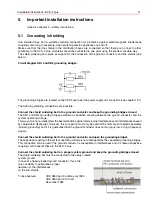
Circuit diagram DB1 and DB2 grounding bridges:
The grounding bridges are located on the CPU board near the power supply unit connector (see chapter 15.1)
The following shielding connections are possible:
Connect the shield soldering bar to the ground conductor and keep the grounding bridges closed
The DB1 and DB2 grounding bridges establish a capacitive coupling between the ground conductor and the
system operating voltage.
This way of wiring normally offers the best protection against mains-borne interferences and interferences caused
by cable shield discharges. However, this connection must only be used if PE and N are connected separately
(modern grounding) and if it is guaranteed that the ground conductor does not carry any low- or high-frequency
signals.
Connect the shield soldering bar to the ground conductor and open the grounding bridges
The capacitive coupling to the system operating voltage is now interrupted by the separated grounding bridges.
This connection can be used if the ground conductor is susceptible to interferences and it is feared capacitive
coupling could transmit these to the ACS-2 plus.
Connect the shield soldering bar to a proper system ground and keep the grounding bridges closed
The shield soldering bar must be connected to the newly created
system ground.
In case of a heavily loaded ground conductor, this is the
only possibility to guarantee a proper
deviation of the interferences
on the line shields.
To be observed:
VDE 0800 part 2 edition July 1980
VDE 0800 part 2 AI draft
November 1982
Summary of Contents for 026547
Page 2: ... ...
Page 42: ...42 Installation instructions ACS 2 plus Connection component mounting diagram ...
Page 58: ...58 Installation instructions ACS 2 plus 14 2 ACS 2 plus structure ...
Page 88: ...88 Installation instructions ACS 2 plus ...
Page 89: ...Installation instructions ACS 2 plus 89 ...
Page 93: ...Installation instructions ACS 2 plus 93 ...

