12
Installation instructions / ACS-2 plus
5.2
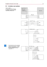
Shielded lines
-
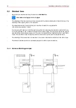
Die ACS-2 plus devices are daisy chained via a
shielded line
.
Use cables of category Cat 5 or higher!
-
The shielding of the incoming line is to be connected to the shield soldering bar of the ACS-2 plus. The
shielding of the outgoing line is not connected.
-
The shield terminal bar in each ACS-2 plus must be connected to a separate PE.
(min. cable cross-section 1,5mm²)
If, when using 12V devices, it is technically not possible to connect ground potential to each ACS-2 plus,
it is recommended to use a three wire cable for the power supply. The third core carries the ground
potential of the common power supply unit. This wire is connected to the shield terminal bar in each ACS-
2 plus. This method is only a temporary solution and should only be used in exceptional cases.
-
The shielding of the reader line is connected on one side to the shield terminal bar in the ACS-2 plus.
-
The above mentioned points also principally apply to the ACS-2 plus module bus .
5.2.1 General shielding principle:
Summary of Contents for 026547
Page 2: ... ...
Page 42: ...42 Installation instructions ACS 2 plus Connection component mounting diagram ...
Page 58: ...58 Installation instructions ACS 2 plus 14 2 ACS 2 plus structure ...
Page 88: ...88 Installation instructions ACS 2 plus ...
Page 89: ...Installation instructions ACS 2 plus 89 ...
Page 93: ...Installation instructions ACS 2 plus 93 ...

