Installation instructions / ACS-2 plus
29
Table 2: Protocol and Baud rate
6
7
Function
Connected to
Comment
0
0
Setup via terminal
program
e. g. Event protocol (for
ethernet)
The switch positions 1-7 are
ignored (see chapter 11).
0
1
9-Bit-Protocol = factory
setting
With these protocols, the
baud rate is set at 19200.
1
0
DIN-66090-Protocol
Interface converter
COMx
1
1
RDT-Protocol
Modem
ISDN card
0 = OFF
1 = ON
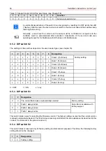
Table 3: Service function
8
Function
0
Factory setting (= service function not active / switch positions 1 - 7 according to table 1 and 2)
1
Service function (meaning of the switches 1 - 7 see table 4)
Warning!
Switch 8 is reserved for service level functions and should
not be changed from the factory setting of OFF. Changing the
switch setting may cause loss of data.
Do not change factory settings!
Table 4: functions with the service switch activated
1
2
3
4
5
6
7
8
Function
1
1
1
1
1
1
1
1
Bootstrap
If the switch 8
ON state
is detected, LED 1 on the CPU board flashes green until the next reset is carried out.
The flashing green LED indicates that a function is in process. When this LED lights permanently, the function
has been completed
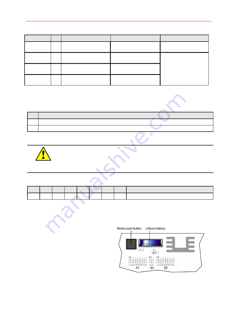
Procedure of bootstrapping:
1. Set all DIP switches to ON
2. Reset (reset push-button)
3. LED 1 flashes (wait)
4. LED 1 lights permanently
5. Switch DIP S1 to the required
position (baud-rate, address,
protocol, etc.)
6. Reset (reset push-button)
Summary of Contents for 026547
Page 2: ... ...
Page 42: ...42 Installation instructions ACS 2 plus Connection component mounting diagram ...
Page 58: ...58 Installation instructions ACS 2 plus 14 2 ACS 2 plus structure ...
Page 88: ...88 Installation instructions ACS 2 plus ...
Page 89: ...Installation instructions ACS 2 plus 89 ...
Page 93: ...Installation instructions ACS 2 plus 93 ...

