54
Installation instructions / ACS-2 plus
12. Outputs
12.1 Semiconductor outputs
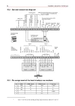
The ACS-2 plus board is provided with 3 semiconductor outputs:
The
output 5 (terminal 24)
and the output 6 (ST 5-3) are freely programmable via NetEdit.
The
watchdog output (ST 5-2) signals (12V) that at least one watchdog reset occurred
since the last hardware reset.
Transistor in common collector circuit.
Two conditions are possible:
- Transistor conducting ( approx. 12V DC at the output).
- Transistor blocking (open output).
To be observed:
Max. current carrying capacity = 50 mA,
short-circuit proof.
12.2 Relay outputs
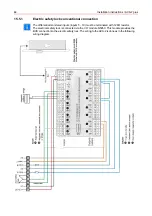
The ACS-2 plus is fitted with 4 potential-free relay outputs with the following factory settings (see 15.1):
2 door strike relays
The connected strikes with load current function can be checked for tampering (see also
chapter 15.4.1).
1 tamper relay
(activated when tampering occurs).
1 alarm relay
(activated during operation. It is released in case of an alarm or
when disconnected from the power).
An alarm is released when a watchdog reset occurs while the jumper ST8 is connected.
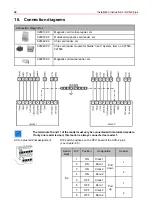
If the ACS-2 plus fails once, the relays 1 and 2 are so defined that the doors remain closed. It is not possible
to change the definition of these relays. The status of relay 3 (alarm) und relay 4 (tamper) can be defined using
jumper ST16.
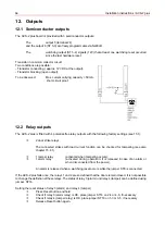
Setting the reset status of relay 3 (alarm) and relay 4 (tamper):
Press Reset button and hold
Check if relay 3 (alarm relay) is OK, place jumper ST16 on 2-4 or 4-6, if necessary
Check if relay 4 (tamper relay) is OK, place jumper ST16 on 1-3 or 3-5, if necessary
Release Reset button again.
Summary of Contents for 026547
Page 2: ... ...
Page 42: ...42 Installation instructions ACS 2 plus Connection component mounting diagram ...
Page 58: ...58 Installation instructions ACS 2 plus 14 2 ACS 2 plus structure ...
Page 88: ...88 Installation instructions ACS 2 plus ...
Page 89: ...Installation instructions ACS 2 plus 89 ...
Page 93: ...Installation instructions ACS 2 plus 93 ...


