46
Mounting and Operating Instructions Doorguard for MB panels BUS-2
14
Required software: MB24/48/100 from V18.xx, MB-Secure fromV04.xx (see 1.2.2))
10.5.4
Signalization via acoustical and optical message
If the input (DG2) is triggered in the active state and depending on the corresponding programming a local
acoustical and optical message is triggered immediately. The red LED "Activation" lights up (static) until the door
is closed and the acoustical and optical message has been stopped.
The duration of the acoustical message depends on the programming:
-
Till alarm is stopped
or
-
Duration 3 minutes maximum
The activation of the "trigger" LED and the output of an optical and acoustic alarm depend on the
operating condition of the intruder alarm control panel (armed / disarmed)
. In armed condition
there are no actuations and outputs. The condition of the inputs will be transmitted independent of the
arming condition of the panel.
10.5.5
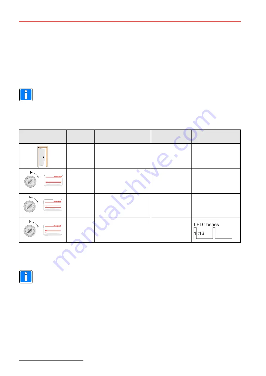
Stop acoustical and optical message
Operating
9
Sequence
9
Duration
Operating state
Red LED
"Activation"
Green LED
"Operating state
"
Doorguard active
Signalization:
- acoustical and
- optical message
Lights up (static)
Lights up (static)
or
1)
1. Pulsed
Doorguard active
Stop acoustical message
Lights up (static)
Lights up (static)
or
1)
2. Pulsed
Doorguard active
Stop optical message.
Door open
–>LED lights up
Door closed
–>LED off
Lights up (static)
or
3. Pulsed
Doorguard inactive
Door open
–>LED lights up
1)
Depending on the condition of the solder bridge
(see Chapter 5.1)!
If the bridge is closed:
Stopping of acoustical and optical message in one common step (only 1 operating
step). A 2nd actuation is therefore not required.
14
Alarmes can also be stopped Via an operating unit at BUS-2.
In this case via the programming can be defined, wether the alarmes can be stopped at every time or only
if the door is closed.


