
1.
General
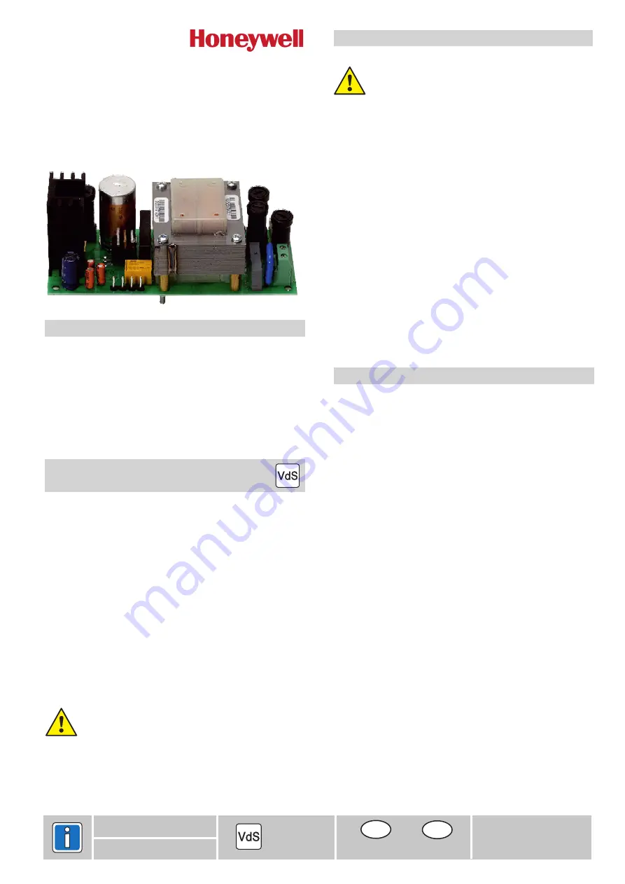
Fully electronic mains/charger unit.
- Voltage-stabilized
- Current limited
- Redundancy standby operation
- Accumulator capacity up to max. 7,2 Ah
When selecting the size of housing, pay attention to the
space required for the accumulators.
2.
VdS guidelines for power supply
The power supply must be connected to the mains with a
separate fuse.
The accumulator used in the power supply must be
approved.
The accumulator must be fixed on the housing base using
Dual lock fasteners
If the electrical installation has an earth-leakage circuit breaker
(Fl switch), the energy supply must have its own earth-leakage
circuit breaker. The fuse and Fl switch should, if possible, be
within the security zone.
If the energy supply is not part of the control panel, it must be
installed in the immediate vicinity (without a space between) so
that an attack on the connection line is impossible without
causing mechanical damage to the housing. The control panel
and power supply should, if possible, be screwed together.
Users not belonging to the system should not be connected to
the mains voltage.
(Item no. 055280).
with this
power supply.
Parallel connection is not possible
3.
Mounting
Attention
Safety instructions
When performing installation work of any kind, the unit must
be de-energized.
When installing the power unit in a control panel housing or
equivalent, ensure that the supplied
. Note, that the power unit is screwed tight to the
housing base.
The non-fused earth conductor from the electric power circuit
must be connected in the immediate vicinity of the connection
terminals of the supply voltage.
The power supply line must be fixed when connecting so that
the clearance (4 mm) and creep paths (5 mm) between the
electronic modules and/or their periphery and the power
supply line are not shorter than stipulated.
If the neutral line cannot be clearly identified, a second pro-
tection must be available in the electric power circuit so that
2-pole separation from the electric circuit is possible.
The connection terminals must be protected against touching
inadvertantly by using the supplied cover.
insulating foil has been
inserted between the housing base and the underside of
the PCB
4.
Functional description
The power unit comprise the voltage supply on the one hand
for the control panel and external user and the accumulator
charger unit for max. 1 accumulator 7.2 Ah on the other.
A maximum of 0.5 A constant current can be generated from
the output for supplying the control panel and the output "Ext.
user". The output "External user" has an upstream 0.63 AT
fuse.
The accumulator charging current is limited to 0.13 A. The ac-
cumulator charging voltage is set at 13.8 V before leaving the
factory. For measuring the accumulator charging voltage, a
4k7 resistor should be soldered parallel to both measuring
points. For this purpose, the accumulator and the 4 pole con-
nectors to the control panel should be disconnected from the
power supply pack.
The supply voltage for the control panel and external user does
not require adjusting. Fault signals are transmitted via the out-
put "Fault" during power or accumulator failure (missing or de-
fective accumulator) with a high signal (+potential).
The output "Mains" is active high (+potential) during power on.
The connected accumulator is protected by a 1.25 AT fuse.
G190702
Subject to change
without notice
Seite 1 - 2 Page 3 - 4
D
GB
Mounting and Connection Instructions
Mains/charger unit 12 V DC / 7.2 Ah
Item no. 057530.10
P00201-10-002-07
2012-04-20
In accordance with VdS standards, the 057530.10 may be used
as an external power supply only in conjunction with an appro-
ved transmission unit, in order that the transmission of the
supply unit fault signals to the corresponding Class A control
panel is ensured.


