background image

61-86-03-13 

Page 3 


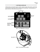
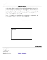
Local Display and Keypad 

 
Configuration and set-up is through the local HMI, consisting of a display and keypad interface (Figure 2).  A high intensity 
10-character LED display and simple pushbuttons provide quick access for actuator set up and status information.  If relay 
outputs are specified, all configuration can be done through either the local HMI interface.  If mechanical switches are 
specified, then the user must manually set the auxiliary output. 
 

DISPLAY

MAN/AUTO

FUNCTION

SET UP

STALLED

ALARM

MANUAL

AUTO

Upper Display
(Four Characters)

Lower Display
(Six Characters)

LED Status
Indicators

Control Arm Rotation

Indicators

CCW

CW

Pushbuttons to
Access Actuator

Set Up, Status and
Calibration
Parameters.  


Figure 2  Local HMI (Display and Keypad) 

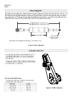
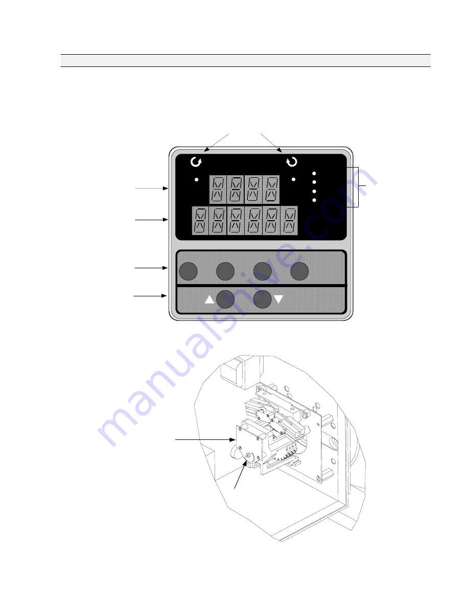
Non-Contact Sensor Spoiler

Non-Contact Sensor

Sensing PW A


Figure 3  Non-Contact Sensor Assembly


Summary of Contents for 11280S

Page 1: ...o demand signal A double reduction worm gear set combines with a variable speed motor controller inverter that is continuous duty rated for accurate and repeatable positioning of final control elements The worm gear set combination also functions as a brake capable of holding greater than two times the output torque in a back driving condition Control options are available to interface with a modu...

Page 2: ...ided and is programmable to provide override of all other input signals as an emergency override of control The digital input can be programmed to drive the actuator open closed remain in place or to a user specified position on contact closure Failsafe When input signal exceeds high or low range limits or input signal failure the actuator can be programmed to drive open closed remain in place or ...

Page 3: ...n can be done through either the local HMI interface If mechanical switches are specified then the user must manually set the auxiliary output DISPLAY MAN AUTO FUNCTION SET UP STALLED ALARM MANUAL AUTO Upper Display Four Characters Lower Display Six Characters LED Status Indicators Control Arm Rotation Indicators CCW CW Pushbuttons to Access Actuator Set Up Status and Calibration Parameters Figure...

Page 4: ...act closure can be wired to external annunciators or alarm points to indicate conditions for any of the Relay Types RTYPnn Relay Type Input Range Position Range Deviation Upper or Lower Limit Travel Temperature High or Low Motor Starts Motor Stalled Manual Mode Power Up Test Failure Input Signal Failure Position Sensor Signal Failure Digital Input Closure RnnE Relay Count Multiplier RnnVAL Relay V...

Page 5: ...umulated Motor Stall Time STARTS Accumulated Motor Starts RLnCNTS Relay Cycle Counts REGNn Accumulated Motor Starts Regions of Travel TOTDEG Total Degrees of Motor Travel MANRST Reset Maintenance Statistics Specifications General Physical Enclosure Precision machined ductile iron with corrosion resistant paint Gear Train Precision machined double reduction worm gear Operating Temperature 30 C to 6...

Page 6: ...al Mains Supply 115 220 Vac single phase 50 60 Hz up to 1500 lb ft 208 200 240 380 480 575 Vac three phase 50 60 Hz Motor Inverter rated continuous duty C face mounting Motor Current Motor Size Full Load Amps FLA Horsepower 230 Vac 460 Vac 1 1 2 3 1 6 2 2 2 6 4 4 5 6 7 8 0 8 1 1 1 3 2 2 2 8 3 9 Loss of Power Stays in place Local Auto Manual Switch Allows local manual and automatic operation of the...

Page 7: ... and low pass filters Solid State Motor Control CW CCW open collectors opto isolators for use as discrete control inputs to the inverter for motor operation Failsafe operation If input signal exceeds configured input range Selectable and adjustable Feedback signals Output 0 to 20 mA 4 to 20 mA 0 to 5 Vdc 1 to 5 Vdc with 250 ohm resistor 0 to 16 Vdc with 800 ohm resistor Slidewire Emulation Provide...

Page 8: ... Model Selection Guide Pipe Length Linkage Minimum 24in 61 cm Linkage Maximum 240in 610 cm This rod end supplied on Actuator with crank arm Pipe length Overall linkage length minus 20 inches 51 cm Figure 4 Pipe Linkage Kit Actuator Crank Arm The 11280S Series Actuator comes standard with an 8 to 14 adjustable radius crank arm The crank arm uses a standard right hand thread 1 rod end to compliment ...

Page 9: ... for the transformer enclosure 575 Vac 3 Phase For customer applications requiring 575 460 Vac 3 phase operation a step down transformer is mounted in a separate enclosure Model Selection Guide Table I option 6 Figure 6 shows the installation for the transformer enclosure 10 0 254 mm 14 0 355 6 mm 16 0 406 4 mm Ground Stud 120 240 Vac Single Phase Transformer 575 460 Vac Three Phase Transformer Fi...

Page 10: ...SUPPLY Single Phase 120 Vac 50 60 Hz a 240 Vac 60 Hz 200 Vac 50 Hz a Three Phase 200 240 Vac 60 Hz 380 480 Vac 50 60 Hz 575 Vac 60 Hz TABLE II STROKE SPEED Stroke Speed 60 Hz 10 sec 90 degrees 30 sec 90 degrees 60 sec 90 degrees TABLE III MOTOR ORIENTATION See specification 61 86 03 13 for diagrams Motor Right hand floor configuration H W Shaft Horizontal Orientation Left hand floor configuration ...

Page 11: ...adii Standard 0_ _ _ _ _ None 1_ _ _ _ _ Linkage Kit None _0_ _ _ _ Up to 20 ft length customer supplies schedule 40 pipe _1_ _ _ _ Future Option None _ _0_ _ _ Future Option None _ _ _0_ _ Tagging None _ _ _ _0_ Linen Note 3 _ _ _ _1_ Stainless Steel Note 3 _ _ _ _2_ Future Option None _ _ _ _ _0 TABLE IX FACTORY OPTIONS Motor Orientation None 00 RESTRICTIONS Restriction Available Only With Not A...

Page 12: ...61 86 03 13 Page 12 Figure 7 Mounting and Outline Dimensions for 11284S 11285S 11286S 11288S and 11289S Weather Proofed Motor Actuators Right Hand Floor Mounting Handwheel Shaft Horizontal D MTG 616 200 ...

Page 13: ...61 86 03 13 Page 13 Figure 8 Mounting and Outline Dimensions for 11284S 11285S 11286S 11288S and 11289S Weather Proofed Motor Actuators Left Hand Floor Mounting Handwheel Shaft Horizontal D MTG 616 210 ...

Page 14: ...arranties expressed or implied including those of merchantability and fitness for a particular purpose Specifications may change without notice The information we supply is believed to be accurate and reliable as of this printing However we assume no responsibility for its use Honeywell 2004 While we provide application assistance personally through our literature and the Honeywell web site it is ...

Reviews: