COMBINED STEP CONTROLLER INSTALLATION / USER GUIDE
PRODUCT PART NUMBER
240V Combined Step Controller
191180-ZCS
FEATURES
•
Provides 8 volts-free normally-open relay contacts for
simple step control of up to 8 fans or compressor
stages
•
Sequential or cyclic switching sequence
•
Easily set switching delays
•
Six-minute interval between successive starts of any
compressor stage
•
Built-in exercise routines for fault-finding
COMMISSIONING
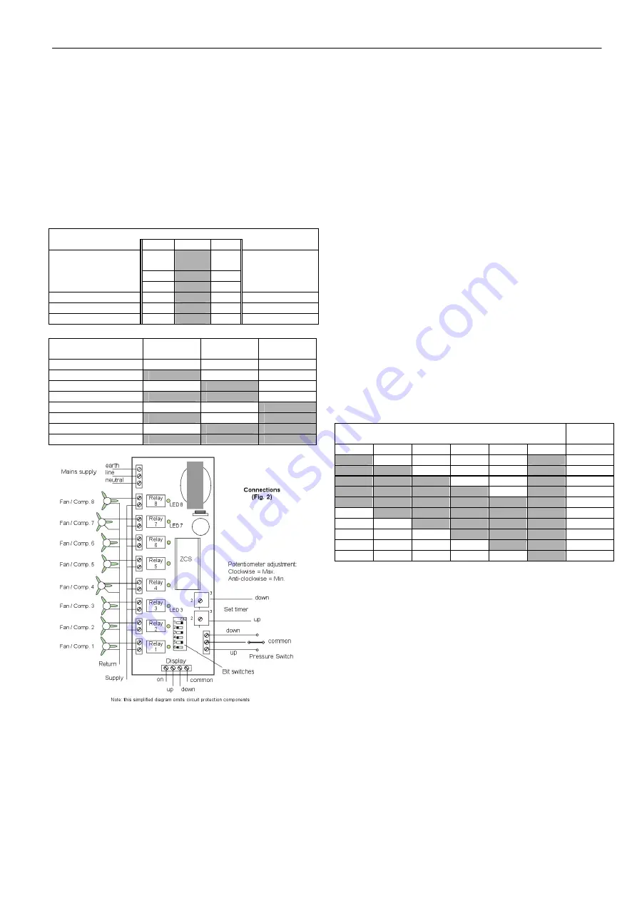
1. Check all electrical connections (Fig. 2)
2. Make sure that the controller software is ZCS
3. Set the Bit Switches (Fig. 1)
4. Switch the controller ON
5. If you choose normal mode:
The first relay is switched on when there is a demand
increase (pressure switch UP), and will be the last to
be switched off when demand decreases (pressure
switch DOWN)
If you choose cycle mode:
The first relay is switched on when there is a demand
increase (pressure switch UP), and will be the first to
be switched off when demand decreases (pressure
switch DOWN)
6. Set the two potentiometers to put a minimum time limit
(i.e. full anti-clockwise), between steps going up and
going down.
- In Fan mode, pot range = 0 to 180 seconds
- In Compressor mode, pot range 20 to 180 seconds
Note: In Compressor mode, same relay cannot
activate twice in six minutes.
7. Faults ?…See ‘Fault Finding’
FAULT FINDING
To exercise the step controller:
•
Switch OFF power to the controller
•
Set Bit Switches 1 to 5 OFF
•
Set Bit Switch 6 ON – for test mode
•
Switch ON power to the controller – Power LED 1
illuminates
•
By setting up the combinations of bit switch positions,
shown in the table you can energise each relay
•
Switch OFF power to the controller
•
If you are not going to check the timers, switch all Bit
Switches OFF now
TO CHECK THE TIMERS
Make sure Bit Switch 6 is ON
•
Switch OFF power to the controller
•
Switch ON power to the controller – Power LED
illuminates
•
Turn Timer 1 (DOWN potentiometer) slowly until Relay
LEDs 1, 2, 3 and 4 illuminate. This should occur
around the centre of the pot range.
Return the pot to the 20 seconds setting. Relay LEDs
1, 2, 3 and 4 will extinguish.
•
Turn Timer 2 (UP potentiometer) slowly until Relay
LEDs 5, 6, 7 and 8 illuminate. This should occur
around the centre of the pot range.
Return the pot to the 20 seconds setting. Relay LEDs
5, 6, 7 and 8 will extinguish.
•
Switch OFF power to the controller
•
After the test, remember to switch Bit Switch 6 OFF to
return to normal operation.
Bit Switch Settings
(Fig.1) (Shaded area = Switch position)
Off
On
Select maximum
number of steps
1
See table Below
2
3
Normal mode
4
Cycle
mode
Compressor mode
5
Fans
mode
Normal Operation
6
Test
mode
Maximum number
of steps
Bit switch 1
Bit switch 2
Bit switch 3
1
OFF OFF OFF
2
ON OFF OFF
3 OFF
ON OFF
4
ON
ON OFF
5 OFF
OFF
ON
6
ON OFF ON
7 OFF
ON
ON
8
ON
ON
ON
Bit Switch
Relay /
LED ON
1 2 3 4 5 6
ON OFF OFF OFF OFF ON 1
ON
ON OFF OFF OFF ON 2
ON
ON
ON OFF OFF ON 3
ON
ON
ON
ON OFF ON 4
ON
ON
ON
ON
ON
ON 5
OFF
ON
ON
ON
ON
ON 6
OFF OFF ON
ON
ON
ON 7
OFF OFF OFF ON
ON
ON 8
OFF OFF OFF OFF ON
ON ALL
OFF OFF OFF OFF OFF ON NONE


