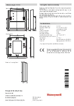
Mounting and Operating Instructions
Contactless reader, s.m.
Item no. 26480.10
Connection
red
black
yellow
red-blue
grey
white
pink
brown
green
blue
grey-pink
violet
Conductor
colouring
026480.10
+12V DC
GND
n.c.
n.c.
clock
data
LED red
LED yellow
LED green
D
D*
RS485EN**
Mounting Information
Between contactless readers must be a minimum distance
of 1 m in all directions.
In outside area we recommend to use the including installation
socket.
Do not install the reader directly on metal as this would
considerably reduce the reading distance. If, however, installation
on a metal surface cannot be avoided, the adapter base item-no.
022196 (see accessories) must be used to achieve the full reading
distance.
Avoid direct sun rays.
The reader should not be exposed to plastic decomposing solvent
vapours.
Address
0
19200
9600
Baud rate
1
6
DIP-switch
Baud rate
0
0
0
-
not placed
placed
-
1
1
Terminating
resistors
0
9
10
DIP-switch
1
1
Terminating resistors
0
0
-
clock/data
RS-485
-
1
1
0
7
8
DIP-switch
0
1
1
Reader mode
Reader
mode
In clock/data mode only
DIP-switch 7 must be set to
ON (position “1”). All the
remaining Dip-switches
must be in position "0" (OFF).
DIP-switches
1
2
3
4
5
6
7
8
9
31
32
Address
DIP-switch
0
0
0
0
0
0
0
0
1
5
0
0
0
1
1
0
0
0
0
1
4
0
0
0
1
1
1
0
0
1
1
3
0
1
1
0
0
0
1
1
1
1
1
0
0
1
1
1
0
0
0
0 0 0
0
0
0
1
2
1
Subject to change
without notice
D
GB
** RS485EN may only be used, if the reader is connected to an
ACS-8 via a potential isolation module (see connection
diagrams of ACS-8 and potential isolation module). In all other
cases this cable must not be connected. The guarantee expires
with wrong wiring, as the device might be damaged or destroyed.
Connection diagrams can be found in the documentations of the
corresponding AC controllers.
LED meaning with AC applications:
LED Basic
After reading Meaning
colour condition a card
yellow on Operation / ready to read
off Device is idle
PIN-Code or door code entry is
active
(only possible with readers with
RS-485 interface)
green on Permanently released
red on Permanently blocked
green on Door release
red on ID card not authorized
red blinking Read error
yellow
Additionally, the key and LED functions of the macro control of IQ
MultiAccess are valid (see separate manual "Supplementary functions
of IQ MultiAccess", P32205-46-0G0-xx).
Meaning of the LEDs
yellow
green
red
P30702-45-002-01
2010-05-05


