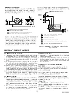
FIG. 1 — DIMENSIONS OF MLx984 VALVE ACTUATOR IN MM (INCHES).
INSTALLATION
Minimum Mounting
3" (8cm) for Actuators with mechanical
auxiliary switches
30 cm (12 in.)
Clearance
Proper Use:
The valves are to be installed by skilled personnel and in strict
accordance with the installation instructions and local regulations.
Honeywell assumes no responsibility for damages or injuries
resulting from non-compliance with installation instructions or
standard good practice when mounting, operating, or maintaining
the valves, even if not expicitly mentioned in the installation
instructions. Observe all safety practices when working with steam
systems.
Mounting:
1. Ensure that the valve body is installed correctly, that is, the arrow
points in the direction of the flow.
2. Although the actuator can be mounted in any position, it is
preferable that it is mounted above the horizontal plane of the
pipe. This will minimize the risk of damage to the actuator in the
event of condensation or a valve gland leak.
NOTE: NEMA 3R rainproof rating only applies to actuators
mounted vertically. Cover has been treated with UV
stabilizers for outdoor applications. Weather-proof conduit
fittings approved for outdoor and wet locations must be
used to maintain NEMA 3R rating.
3. Remove the stem button (Fig. 3) from the valve stem.
4. (Optional) Slide the position indicator (plastic disk or rubber O-
ring) over the valve stem (Fig. 3). Indicator will self-align to the
marking on the yoke after complete operating cycle.
FIG. 2 — MINIMUM MOUNTING CLEARANCE
When Installing This Product...
1. Read these instructions carefully. Failures to follow them could
damage the product or cause a hazardous condition.
2. Check ratings given in instructions and on the product to ensure
the product is suitable for your application.
3. The installer must be a trained, experienced service technician.
4. After installation is complete, check out product operation as
provided in these instructions.
5.
DO NOT electrically operate the actuator before assembly
to the valve because damage not apparent to the installer
may occur.
IMPORTANT
• Before installing the valve, raise and lower the valve stem to
make sure that the valve stem operates freely. Impaired stem
operation can indicate that the stem was bent by rough handling.
This condition can require repair or replacement of the valve.
• Protect the stem from damage due to bending or scratching.
Damage to the stem packing may result.
FIG. 3 — PREPARATION FOR VALVE ASSEMBLY
3
95C-10939-4
Position Indicator
Assembly of the
Valve Stem
Remove Stem Button
NOTE: DO NOT DAMAGE
(Plastic Disk)
ANY PART OF THE STEM.
position indicator.
102
[4.02]
101.9
[0.78]
22 [7/8]
103
[4.06]
82
1/4 - 28UNF
34.7 [1.368
42
5 [0.19] DIA.
10 [0.39]
68.8 (Y
ellow) 71.8 (Silver)
[2.71]
[2.83]
[4.0]
Knockout
20
[3.2]
78
[3.07]
39
[1.53]
1/4 - 20 NUT
[2]
102
[4.02]
51
[2.01]
MOUNTING DIA.
20.5
[0.80]
53.2
[2.09]
7
[0.27]
56
[2.20]
[1.65]
82
[3.22]
19 [0.75]
NORMAL STROKE
77.5
[3.09]
116
[4.57]
178.8
[7.04]

