background image

Precision Platform 4022 Scanner 

Precision Platform 4022 Series Scanner Components 


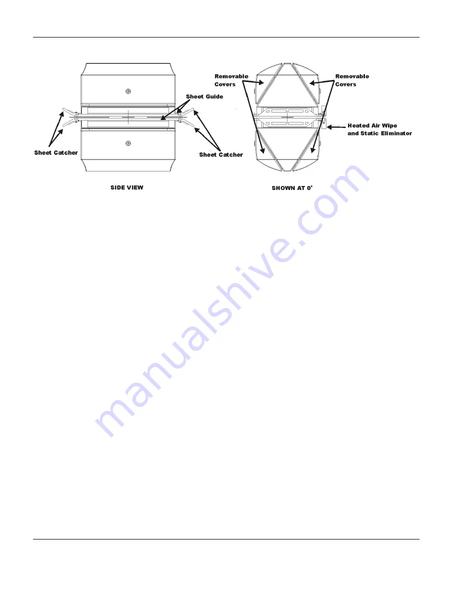
Figure 5-9 PrecisionPak4 Heads 

5.4.2. Outboard heads 

Some sensors can not be mounted within the PrecisionPak4 heads and are 
always mounted outboard of the main sensor heads. These outboard heads 
are mounted to the outside edges of the sheet guides of the main heads and 
have separate environmental controls. The Gloss, Porosity, Color, and 
Caliper sensors are examples of sensors that can be mounted within 
outboard sensor enclosures. New systems have the heads configured and 
installed at the factory, but field retrofits are possible. Check possible sensor 
placements with the Honeywell Configuration Department. 

5.5. Head contents 

Each PrecisionPak head configured for the Precision Platform Scanner 
contains: 


Sensors 


Environmental Control Unit (ECU) 


Sensor Termination Backplane PCB 


Sensor Configuration PCB 


Sheet Guide Heater Circuitry 

 10/4/07 

p/n: 

6510020208 

5-20 

Summary of Contents for 4022

Page 1: ...Precision Platform 4022 Scanner System Manual 6510020208 ...

Page 2: ......

Page 3: ...Precision Platform 4022 Scanner October 2007 ...

Page 4: ...o the best efforts of Honeywell and are believed to be true and correct as of the time of this printing However due to continued efforts in product improvement we reserve the right to make changes at any time without notice To view or order additional or revised copies of this publication visit Honeywell s Process Solutions Center Trademarks All trademarks and registered trademarks are the propert...

Page 5: ... scanners 1 1 1 1 2 Precision Platform for Da Vinci with remote PMP 1 1 1 1 3 Precision Platform for MXOpen 1 1 1 2 Data sheet 1 2 1 3 Differences between 4022 series scanner models 1 4 2 Site Preparation 2 1 2 1 Obtaining the latest scanner installation drawings 2 2 2 2 Choosing a scanner location 2 2 2 3 Allocating space 2 4 2 3 1 Precision Platform dimensions 2 4 2 3 2 PrecisionPak Head dimensi...

Page 6: ...ng mill water or other potable quality water in an open loop system 2 21 2 12 5 Setting up a chiller backed up by an external open loop 2 22 2 12 5 1 Choosing the chiller location 2 23 2 12 5 2 Connecting the chiller to the Precision Platform 2 23 2 12 5 3 Establishing a backup system for the chiller 2 23 2 12 6 Chillers and chiller requirements 2 24 2 12 6 1 Life and warranty 2 24 2 12 6 2 Size a...

Page 7: ... cooling fluid to the Precision Platform 3 14 3 9 2 Installing a water to water heat exchanger 3 14 4 System Testing and Verification 4 1 4 1 Testing for Radiation Safety during installation 4 1 4 2 Testing the Precision Platform operation 4 2 4 2 1 Starting and stopping Precision Platform head movement 4 3 4 2 2 Observing the Precision Platform in motion 4 6 4 2 3 Using the motor controller to tr...

Page 8: ...nd operator controls 5 12 5 3 1 Distant end support 5 12 5 3 1 1 Scan control panel 5 13 5 3 1 2 Sensor shutter status satellite box 5 15 5 3 2 Cable end support 5 16 5 3 2 1 Sample and reference panel 5 18 5 3 3 Scan control switch panel decoder PCB 5 18 5 4 PrecisionPak heads 5 20 5 4 1 Head covers 5 20 5 4 2 Outboard heads 5 21 5 5 Head contents 5 21 5 5 1 Sensors 5 22 5 5 2 Termination configu...

Page 9: ... Miscellaneous interlocks switches and accessories 6 31 6 6 1 Interlocks 6 31 6 6 1 1 Head split interlock 6 31 6 6 1 2 Ash interlock 6 31 6 6 2 Termination board switches 6 31 6 6 2 1 Computer Manual switch S1 6 32 6 6 2 2 Scan Forward switch S2 6 32 6 6 2 3 Offsheet Reverse switch S3 6 32 6 6 2 4 Frame Controller switches 6 32 6 6 3 Sheet guide heater circuitry 6 33 6 6 4 Ash sensor safety inter...

Page 10: ... 9 5 9 2 1 Air pressures and flow 9 5 9 2 2 Air filter 9 5 9 2 3 Air wipe 9 5 9 2 4 Vents 9 5 9 2 5 Maintaining the scanner air purge system 9 5 9 2 5 1 Checking air flow 9 6 9 2 5 2 Checking air inlet filters 9 6 9 3 Power tracks 9 6 9 3 1 Maintaining the power tracks 9 6 9 3 1 1 Inspection of the power tracks 9 7 9 3 1 2 Adjustment of the power tracks 9 8 9 3 2 Replace upper and lower power trac...

Page 11: ...3 Replace AC motor 9 33 9 8 4 Limiting drive motor torque 9 34 9 8 5 Verifying drive motor torque 9 35 9 8 6 Verifying torque setting with motor controller panel 9 35 9 8 7 Adjusting torque with motor controller panel 9 36 9 8 8 Replacing the motor controller 9 36 9 9 Heads and sensors 9 37 9 9 1 Separating the heads 9 37 9 9 2 Realigning the heads after clutch separation 9 38 9 9 3 Head removal a...

Page 12: ... Control Buttons 4 5 Figure 4 5 Multi scanner Control dialog box 4 6 Figure 5 1 Precision Platform 4022 30 31 40 Scanner 5 3 Figure 5 2 Typical Configuration 4022 31 Precision Platform Scanner with Remote PMP 5 5 Figure 5 3 Typical Configuration 4022 30 Precision Platform Scanner with existing MXOpen system 5 6 Figure 5 4 Head Drive System 4022 scanners 5 9 Figure 5 5 Distant end support 5 13 Figu...

Page 13: ...ead Drive Belt Tensiometer 9 22 Figure 9 6 Adjusting the Belt Support Brackets 9 28 Figure 9 7 Clutch Assembly 9 29 Figure 9 8 Motor Wiring Details 9 34 Figure 9 9 Head Separation Clutch Controls 9 38 Figure 9 10 High Pressure Air Manifold 9 43 Figure 9 11 Low Pressure Air Manifold 9 44 Figure 9 12 Head Air Purge 9 45 Figure 9 13 ECU and Temperature Controls 9 48 List of Tables Table 2 1 Minimum S...

Page 14: ...ttings 6 8 Table 6 3 Termination Board LEDs 6 13 Table 6 4 Termination Board Jumpers and Switches 6 13 Table 6 5 Termination Board Fuses 6 14 Table 6 6 Termination PCB signals 6 14 Table 6 7 Logic PCB Jumpers LEDs and Fuses 6 27 Table 6 8 Assemblies used in 4604 02 PMP 6 29 Table 6 9 Boards used in MSS 6 29 Table 6 10 Electronic boards used in MSS PMP assemblies 6 30 Table 6 11 Sheet Guide Jumper ...

Page 15: ...maintenance of Scanner Frame Heads Communications Power Distribution Assembly Precision Measurement Processor PMP Connections between the scanner and the PMP The Da Vinci Server Global User Station MXOpen MXProLine Precision Measurement Processor and the Scanner Support Processor SSP 1 are not documented in this manual 1 For MXOpen and SSP documentation refer to original system manuals whenever po...

Page 16: ...lace before the arrival of the 4022 series scanner Chapter 3 Installation describes the installation and set up tasks for the 4022 series scanner Chapter 4 System Testing and Verification describes various testing and verification procedures Chapter 5 Precision Platform 4022 System Components describes the components of the 4022 scanner system Chapter 6 Precision Measurement Processor describes th...

Page 17: ...onventions are used in this manual i NOTE Text may appear in uppercase or lowercase except as specified in these conventions Boldface Boldface characters in this special type indicate your input Special Type Characters in this special type that are not boldfaced indicate system prompts responses messages or characters that appear on displays keypads or as menu selections Italics In a command line ...

Page 18: ...s to position the mouse pointer on an item then quickly depress and release the mouse button This action highlights or selects the item clicked Double click Double click means to position the mouse pointer on an item then click the item twice in rapid succession This action selects the item double clicked Drag X Drag X means to move the mouse pointer to X then press the mouse button and hold it do...

Page 19: ...al publications The next four digits identify the manual These digits remain the same for all rewrites and revision packages of the manual for a particular product Revision numbers are indicated after the Rev Figures in this manual Figures depicting product diagrams or schematics are included in this manual for illustration and explanation purposes only and may not match the revision of the drawin...

Page 20: ...provide the part numbers descriptions and quantities for the item bubbles shown on the drawings Listed here are the types of drawings and documents typically found on a Document List DL AA09xxxxxxA indicates a model number assembly drawing Drawings of this type are used when lower level assembly drawings are not required AA09xxxxxxS indicates a model number assembly schematic AA09xxxxxxI indicates...

Page 21: ...in other areas The Table of Contents for the drawing package is organized into two sections The first section lists the model numbers in numeric order The second section lists the documents and drawings in alphanumeric order that is the documents and drawings are listed by increasing part number and are organized by 05 08 09 and 65 drawings MNs ASs and other relevant documents are also provided Ho...

Page 22: ......

Page 23: ...ision Platform for Da Vinci with remote PMP The 4022 31 and 4022 40 models both have a Precision Measurement Processor PMP located in a compact remote wall mounted enclosure that interfaces directly with the Da Vinci or MXProLine for 4022 40 control system 1 1 3 Precision Platform for MXOpen The Precision Platform 4022 30 interfaces directly to the existing MXOpen system where sensor signals are c...

Page 24: ...rements Quality Potable Water or ethylene glycol potable water solution Min Pressure 2 7 BAR 40 PSI Max Pressure 4 1 BAR 60 PSI Max Temp 30ºC 86ºF Max 7 6 L min 2 gal min Exact flow varies with conditions Beams Wide Flange Structural I Beam W10x45 Maximum Beam Length Standard Up to 8 5 m 336 longer length available upon request End Supports 13 mm 1 2 gusseted steel plate Scanner Mounting Bottom mo...

Page 25: ...atus Indicators Top mounted shutter status for basis weight ash on both end supports as applicable Controls Distant End and Cable End emergency stop button Distant End Scan and off sheet caliper enable disable if applicable Cable End Head separation key switch reference sample switch Can be reversed when tending side is opposite end of the scanner Resolution of Sensor Head Position 0 022 mm 0 0009...

Page 26: ...2 31 40 only 30 5 m 100 ft N A Sensor Signal Digitization 400 Hz 2nd Order anti alias filter 2000 samples sec 512 kHz VFC with pulse counting Signal Processing Calculation of Average Voltage per Measurement Zone PMP CPU Conversion to Engineering Units Da Vinci MXProLine Application Server Calculation of Total Counts Per Measurement Zone and Conversion to Engineering Units MXOpen SSP Profile Resolu...

Page 27: ...scanner installation drawings Choosing a scanner location Allocating space Building mounting pedestals Obtaining lifting equipment Installing cables conduits and cable trays Providing a safety ground Providing AC power including power quality and DC power supplies Providing communications network Connecting field wiring Providing low pressure purge air if required including blowers and motors and ...

Page 28: ...in the most recent version of the Precision Platform installation drawings These drawings will include the most recent dimensions and specifications for installation and should be used when preparing the site for installation The latest drawing set is shipped with the system All Honeywell Field Project Managers have direct internet access to sites where drawings are stored Drawings can also be obt...

Page 29: ...he scanner Observe the locations and other equipment on the machine that operators must access This is especially true during threading of the machine Some scanner locations may require moving or modifying existing threading rope runs or belts or the addition of threading conveyors to safely thread the machine after the addition of the scanner The location of the scanner is also determined by the ...

Page 30: ...will likely come up through the floor adjacent to the scanner pedestal High pressure air and coolant also is best routed from below however the filters and air pressure regulators should be located as near the scanner as practical Filters and regulators can be mounted on an adjacent wall The plumbing to the scanner can be routed under the floor to the scanner Depending on scanner environment the c...

Page 31: ...38mm 33in Allow another 1 cm 1 2in for leveling shims The recommended pedestal design is shown in the installation drawings Precision Platform beam length is site dependent The scanner is available in standard lengths between 4 6 and 8 5m 10 and 28ft Any beam length over 8 5m 28ft is not standard and requires Honeywell engineering assistance The length at a particular site is a function of paper r...

Page 32: ...ter and subject to occasional splatter CAUTION Do not use pressure washers on beam covers while installed on the scanner as this may allow water or contaminants into the sensor heads In cases where the doors lack enough clearance to swing fully open the distant end door can be reversed to hinge on the opposite side or removed by lifting the door off the hinges enabling better access The cable end ...

Page 33: ...the height required by the sheet passline The passline height and head angle depend on the height and angle of the adjacent rolls These passline measurements can be determined by stretching a length of twine tightly over the rolls The pedestals must place the middle of the air gap between the heads at the height and angle of the twine The height of the pedestals can be calculated by subtracting 83...

Page 34: ...be the center of gravity as the cable end of the scanner is heavier The angles of tilt depend on the particular site configuration WARNING Do NOT plan to exceed a 10 angle of tilt for the lifting cables or the scanner unless you have specifically consulted with Honeywell personnel about this issue The supplied lifting eyes are rated only for a 10 angle of tilt Be sure to choose the proper lifting ...

Page 35: ...lication Server must be fabricated The maximum length of the PrecisionNet cable between the PMP and the Application Server is dependent On the type of Ethernet cable used but may be as small as 90m 300 ft without repeaters if 10BaseT twisted pair cable is chosen Repeaters or another cable type must be used for longer distances A chart of Ethernet media and maximum cable lengths is provided on the ...

Page 36: ...tions to facilitate cable pulling and to minimize the risk of cable damage Per NEC specifications size the pull boxes to provide adequate space for all conductors in each box Do not fill conduits more than 40 of full 2 6 2 Installing cable trays The following cable tray requirements either meet or exceed the NEC specifications for ensuring a protective passageway for the system cables All installa...

Page 37: ...nnecting cables must be suitable for use on cable tray systems and satisfy the requirements of NEC Article 725 for Class 2 and Class 3 circuits Honeywell cables cannot be run in the same cable tray system as Class 1 power lighting and control cables Route trays carrying Honeywell cables as far away as practical from Class 1 power lighting and control cables as well as from cables carrying frequent...

Page 38: ...tential between the scanner and surrounding conductive equipment and the resultant possibility of electrical shock The safety ground should be 6 AWG wire to easily conduct the maximum current possible with an accidental ground fault The ground should be local and not remote to ensure the potential is common to adjacent equipment 2 8 Providing AC power The Precision Platform must be supplied with A...

Page 39: ... may result in non sinusoidal current waveforms Measurements must always be taken using a true RMS current meter For true RMS requirements assume that the power supplies have a worst case current crest factor of approximately three 2 9 Providing the communications network The maximum cable length between the PMP and the Da Vinci Application Server depends on the type of cable used for PrecisionNet...

Page 40: ... no warmer than 48 C 120 F Pressure 2 5cm 1in of water minimum Filtered source the air from a low dust location and filtered The air enters the scanner frame through ducting that must be attached to the collar at the top of the cable end support as shown on the installation drawings Air flow through the end support escapes through the beams The ducting and purge air system should be provided and s...

Page 41: ...rument air The scanner head heated air wipe and sensor activation systems require clean dry compressed high pressure instrument quality air supplied through each power track The high pressure air requirements are Pressure 4 8 6 9 Bar 70 100 psig minimum Flow rate 142 145 l minute 5 15 cfm maximum Quality as per ISO 8572 l 222 The flow required is dependent on the installed sensors The air enters t...

Page 42: ...automatic water drains and coalescing after filters 2 12 Providing external cooling fluid The heads and cable end electronics module are cooled with circulating fluid and air The manner in which fluid is supplied to these systems depends on local site conditions and the sensors to be used in the particular system 2 12 1 Head temperature control with coolant An Environmental Control Unit ECU is loc...

Page 43: ...ted on top of the ECU to measure the internal air temperature The internal head air temperature setpoint is set on this trim controller see Table 2 4 Head internal temperature should be held constant between 38 C 100 F and 49 C 120 F and most importantly should vary less than 1 C 1 8 F Under most conditions the ideal internal head temperature is 40 C 104 F When the temperature rises above limits t...

Page 44: ... W1 on the power track termination board see Table 2 5 Table 2 5 Sheet Guide Heater Jumper Setting Sheet Guide Heater Configuration W1 Jumper Setting Sheet Guide Heaters Always On W1 A Sheet Guide Heaters Only On when Heads Parked Offsheet W1 B Sheet Guide Heaters Always Off None On the 4022 30 and 4022 31 scanner models the sheet guides are further heated with heated air wipes The temperature of ...

Page 45: ...on through a coolant to air heat exchanger to control the temperature of the air The coolant flows from the intake manifold into the back of the PMP electronics enclosure The circulation fans run continuously and the coolant flow is on off controlled by a thermostat using a normally open solenoid The temperature is thermostatically controlled to 38 C 100 F and cannot be adjusted The PMP electronic...

Page 46: ...for local conditions Table 2 7 Configurations for Cooling Heads and PMP Enclosure Depending on Site and System Characteristics Potable Water Coolant Supply Temperature Cooling Configuration Honeywell Part Number Comments Yes 30 C 86 F Mill Supply Open Loop n a Ensure water is potable No 27 C 80 F Heat Exchanger Closed Loop 26000175 No 30 C 86 F Chiller Closed Loop 26000191 60 Hz 26000192 50 Hz Hea...

Page 47: ...e planned location of the cable end support Limit the pipe run to approximately 15 m 50 ft Insulating the pipe is strongly recommended if its length exceeds 10 m 30 ft The piping should be at approximately floor level and the drain should not be above the level of the scanner No fluid line hookup is required at the heads The power tracks are already connected to hoses that enter the heads 2 12 4 U...

Page 48: ...g up a chiller backed up by an external open loop Cool the heads and cable end electronics with fluid supplied in an external closed loop from a chiller or heat exchanger The proper temperature and purity of the cooling fluid can be ensured in a closed loop A chiller supplied system must be backed up by an open loop water system If the chiller will be in an environment with ambient temperatures un...

Page 49: ... chiller lifetime Place Chillers in clean locations to prevent dust buildup on the condenser fins 2 12 5 2 Connecting the chiller to the Precision Platform External coolant sources connect to the Precision Platform by way of hoses that must be attached to the scanner s air and coolant supply manifold at the cable end support From this manifold the fluid passes to the heads by way of the power trac...

Page 50: ...voir The backup source should be teed to the Precision Platform at both the return and the supply hoses at the cable end support It is essential to ensure that fluid from the chiller and fluid from the external open loop never mix 2 12 6 Chillers and chiller requirements 2 12 6 1 Life and warranty The chiller should be minimally capable of continuous operation over a five year life span and should...

Page 51: ...nd other damage All steel parts should be galvanized or double coated with a zinc based epoxy undercoat and two epoxy or polyurethane overcoats Condenser fins should be aluminum or copper These fins are usually very thin and are subject to corrosion They can be polyurethane coated to provide extra corrosion resistance but this reduces cooling capacity Consult mill maintenance personnel to ensure t...

Page 52: ...t the Precision Platform will be protected from process operations and operation byproducts Provide shielding to prevent sizing from splashing onto the scanner Provide preventive maintenance procedures and schedules for Spraying the shields with water to prevent buildup and to recirculate the sizing Removing broke to prevent buildup Providing general cleaning to remove grit and grime 2 14 Ensuring...

Page 53: ...N status Safe operation of the head split mechanism 2 14 2 Where to find information on radiation safety 2 14 2 1 Radiation safety training manual for customers While this manual includes references to appropriate safety and regulatory requirements because scanners include sensors that use radiation sources Honeywell strongly recommends that become familiar with the information provided in the Rad...

Page 54: ...safety testing Required qualifications for personnel involved in installation use service and testing of sensors containing radiation sources Maintenance procedures cleaning sensor heads for example Separation or removal of heads containing radiation sources Changing sensor air gaps Replacement of radiation source window in sensor head Modifications to sensor heads interlocks and other safety feat...

Page 55: ...X ray sources must be knowledgeable of and trained in the proper safety methods for X ray devices In most locations a permit or registration is required to maintain service and install X ray devices Failure to follow radiation safety procedures MAY cause exposure to hazardous levels of radiation 2 15 Scheduling Installation Personnel Honeywell recommends that a variety of maintenance actions be pe...

Page 56: ...garding radiation safety to Radiological Operations The main contact numbers for Radiological Operations are First level of support The Americas Asia Pacific and India are supported directly by Phoenix at 602 313 3330 Europe Middle East and Africa are supported by Waterford at 353 0 51 372 151 Second level of support world wide is Phoenix at 602 313 3330 Phoenix also has a toll free number for the...

Page 57: ...nd radiation safety Storing the Precision Platform and radioactive sources after receipt Preparing the mounting hardware Lifting and placing the Precision Platform with a crane Bolting down and leveling the Precision Platform Preparing the expansion joint Cabling the Precision Platform Connecting air sources Connecting the cooling fluid Powering up and verifying the Precision Platform is online ...

Page 58: ... Leave it as received and contact the factory and shipping company 3 2 Receiving radioactive sources and radiation safety Additional information on radioactive and X ray sources and safety is available in the Radiation Safety Training Manual Honeywell p n 6510020199 If licensed personnel have not been scheduled to perform the installation procedures and tests that involve radioactive sources make ...

Page 59: ...eads Information on licensing and regulatory requirements that apply to OEMs and end users is available in the Radiation Safety Training Manual Honeywell p n 6510020199 3 2 1 Receiving radioactive sources Shipping containers containing basis weight assemblies with radioactive sources are clearly labeled to identify their contents PrecisionPak heads are not certified containers for transportation o...

Page 60: ... installation the shield must be removed by an individual who is specifically authorized to do so under terms of a radioactive materials license WARNING All shields must be removed from radioactive sources before power to the scanner is turned on 3 3 Moving the Precision Platform Care must be taken while moving the scanner on the dollies Do not allow the scanner to be twisted by letting the two en...

Page 61: ...the Precision Platform The Precision Platform is shipped with dollies that can be used to roll the scanner to the installation location where it will be lifted onto the mounting pedestals See Figure 3 1 WARNING Scanners are heavy To avoid personal injury use caution when unbolting and removing the dollies 3 5 1 Attaching the Precision Platform to a crane In the case where the scanner s length does...

Page 62: ...a single crane a spreader or yoke must also be used so the cable angle does not exceed 10 Scanners include a set of eyebolts at each end and one third of the scanner length in from both end supports The scanner can be lifted from either the inner or outer eyebolt locations If slings of any sort are to be used they must pass under the upper beam between the fiberglass head drive track and the beam ...

Page 63: ... possible WARNING When the scanner is lifted the vertical angles of the scanner and the lifting cables must never exceed the angles that were anticipated when the scanner was initially attached to the crane Any angle farther off the vertical than anticipated could cause the eyebolts or other elements to fail or slip 2 Lower the scanner onto the pedestal 3 Place string between the two turn rolls on...

Page 64: ...ring This is done by loosening the three bolts at each head angle adjustment arc Use the provided gap spacer bars to ensure the two heads are parallel 5 When the head angle is set and the scanner is leveled tighten the bolts holding the scanner to the mounting pedestals to 50 ft lbs of torque The bolts should not be so tight as to prevent the expansion joint from functioning 6 Remove the shipping ...

Page 65: ...ed and shimmed on the pedestals remove the 3 8 16 shipping bolts Figure 3 2 Expansion Joint 3 7 Cabling the Precision Platform All cabling to the Precision Platform is routed through the termination panel at the cable end of the scanner For details refer to the installation drawings To provide cables with the best mechanical protection run them in steel or aluminum conduit never plastic If cable t...

Page 66: ...ad shipping strapping must be removed from radioactive sources before power is turned on to the scanner To connect AC power and communications cabling to the Precision Platform 1 Connect the scanner safety ground first 2 Run conduit and a three conductor cable from a dedicated 25 Amp plant circuit breaker to the ground fault interrupter circuit breaker at the bottom of the cable end Use a short ru...

Page 67: ...ternals The air can also be used for cooling the drive motor however if the purge air is too cold it may cause condensation on the outside of the scanner Should condensation occur reduce the flow rate of the air to the scanner through ducting To connect the scanner purge air the ducting must be attached to the eight inch duct collar at the top of the cable end support shown in the respective insta...

Page 68: ...ns for two compressed air supplies The mill air must be plumbed to two different filter regulators and then from the filter regulators to the scanner Two filter regulators are used to supply air to the scanner The first supplies a higher volume flow of compressed air to the heads The higher volume air is used for air wipes and sheet stabilizers The second filter regulator supplies low volume compr...

Page 69: ... much and condensation forms on the scanner covers reduce the air flow from the blower using the damper until the condensation is reduced to an acceptable level non dripping or increase supply air temperature 3 9 Connecting external coolant fluid If the supply source for cooling fluid to the heads has not yet been determined see Chapter 2 for requirements p n 6510020208 10 4 07 3 13 ...

Page 70: ...upport Refer to the Scanner Installation Drawings 3 9 2 Installing a water to water heat exchanger The procedure for installing a Honeywell water to water heat exchanger cooling system is explained in this section The installation drawing shows the front and bottom views of the water to water exchanger unit including the reservoir level indicator temperature gauge pressure gauge and the in and out...

Page 71: ...rvoir lid and fill the expansion tank with 1 4 gallon 1 liter of Prestone coolant and 8 liters 2 gallons of clean water 6 Turn on the mill water then turn the exchanger unit ON OFF switch to ON 7 Add water to the expansion tank as necessary to bring the water level up to three quarters full Add water after the scanner has been turned on the heads have heated and the temperature control solenoid ha...

Page 72: ......

Page 73: ...g Adjusting sheet guide and air wipe heaters Checking sensor stability Reviewing and recording Precision Platform configuration parameters 4 1 Testing for Radiation Safety during installation Regulations require that an installation radiation safety test be conducted and documented before the installation process is completed and the Precision Platform is made operational This test must be conduct...

Page 74: ...y is available in the Honeywell Radiation Safety Training Manual p n 6510020199 WARNING Failure to follow radiation safety procedures MAY cause exposure to hazardous levels of radiation 4 2 Testing the Precision Platform operation Once the Precision Platform has been installed and set up test the subsystems listed in the order shown and make any needed adjustments as described in the sections Driv...

Page 75: ...ple open and close the shutter 4 2 1 Starting and stopping Precision Platform head movement Movement of the heads can be started and stopped from either the Scan Control Panel on the scanner or on the operator s console Once scanning has started do not proceed beyond the scanner end support A warning placard as shown in Figure 4 1 is prominently displayed at each end support Impact with the moving...

Page 76: ...nner end support door facing out On this panel press Scan to start the heads moving or press Offsheet to return the heads to their parked position Pressing either emergency stop button stops the heads in the current position If the emergency stop button is depressed the scanner will not scan During scanning the cable end support contains moving belts and pulleys and access could cause serious inju...

Page 77: ...th two green arrows or the OFFSHEET picture of a scanner with one red arrow button both located in the Vertical Menu Bar If the system has more than one scanner first select the MULTI SCANNER button picture of three scanners then select the desired scanner from the Select Scanner drop down Menu see Figure 4 5 and then select either the SCAN or OFFSHEET button from the Multi scanner Control dialog ...

Page 78: ...08 2 Observe the 2 digit display on the motor controller located in the PMP for 4022 31 40 scanners located onboard the scanner at the cable end for 4022 30 scanners During normal operation this display indicates the frequency being applied to the motor A frequency of 38 Hertz is about 24 inches sec The controller displays for a stopped motor Momentary display of CL indicates that the controller i...

Page 79: ...scanner There is an over temperature cutout on the PMP MSS that may have cut power to the motor controller All power to the PMP MSS cabinet is cut so you will note no signs of power within the cabinet 4 Test to determine whether or not the scanner can scan in the manual mode a Set the manual computer switch on the bottom of the cable end termination board to Manual Then switch the frame controller...

Page 80: ... motor controller displays CL while in steady state scanning not accelerating a higher current limit might be required for the scanner however for safety reasons do not set the current limit too high An obstruction to scanning or incorrect clearance setting of the wheels on the head carriage would also result in the CL being displayed continuously do not adjust the limit in these cases The procedu...

Page 81: ...ler LED display if it is 8 Check contact outputs for Scan and Direction 9 Use hardware write function to try to scan the heads 10 Verify that the scanner software variables are set correctly 11 Are the Comp Man and Host Shop mode switches set correctly WARNING Do not scan in the maintenance mode This engages the caliper sensor offsheet and will break the sheet Before startup scan on static sheet w...

Page 82: ...st be set high enough so that the scanner always accelerates reliably and smoothly 4 2 5 Verifying torque setting with motor controller panel The AC Tech motor controller limits the maximum torque of the three phase motor by limiting the current to the motor Parameter 25 sets this current limit It can be set anywhere between 30 and 180 of the rated maximum current The value entered into parameter ...

Page 83: ...r P N 6580800429 4022 30 31 40 GMO P N 08733705 01 02 02 03 03 01 04 03 05 03 06 08 07 N A 08 01 09 01 10 05 11 01 12 06 13 01 14 01 15 02 16 02 17 02 18 N A 19 3 0 20 0 7 21 0 0 22 0 0 23 0 0 24 30 0 25 75 0 26 75 0 27 80 0 28 0 0 29 39 0 0 40 60 0 41 200 42 20 0 43 01 44 225 47 01 48 01 Values shown in italics indicate factory default settings ...

Page 84: ...s toothed and wraps around drive sprockets The main drive belts are 2 5 cm 1 0 in wide with 1 3 cm 0 5 inch pitch neoprene rubber reinforced with fiberglass cable The main drive belt tension requires adjustment at the following times When the heads do not hold the cross direction alignment When the head drive belts have been replaced When the belts have stretched unequally Tension on the top and b...

Page 85: ...head alignment pins If the pins do not go through both heads with the heads located on both the scanner cable and drive ends the heads are not properly lined up See Subsection 9 6 3 and Subsection 9 6 4 for head alignment procedures CAUTION The head alignment pins must be removed before going onsheet 4 2 7 2 Verifying vertical direction head alignment Leave the head alignment pins in the upper hea...

Page 86: ...d standardize or go directly to scanning depending on the scanner setup settings Once scanning press Offsheet to ensure the scanner goes offsheet and to the correct parked position Once the scanner scans correctly the heads are taken offsheet and it verifies that all other scanner outputs and inputs are functioning This test is performed by pressing buttons and reading the input buffer or by check...

Page 87: ... violate the setpoint This may occur if part of the fluid circulation system fails See Section 9 10 for troubleshooting the cooling system Head internal temperature should be held constant between 32 C 90 F and 43 C 109 F and most importantly should vary less than 1 C 1 8 F Under most conditions the ideal internal head temperature is 40 C 104 F When the temperature rises above the 49 C 120 F limit...

Page 88: ...ed on the heating element protects the unit from overheating These embedded heaters can either be on all the time off all the time or on only when offsheet One of these three settings is selected by a jumper on the end bell termination board Once their power is connected the heaters produce a constant level of heat However heat levels from the air wipe system vary in response to changing ambient t...

Page 89: ... next subsection 4 5 2 Adjusting the setpoint of air wipe heaters The air wipe heater in the ECU of each head controls the temperature of the air that heats the sensor windows and sheet guide The air wipe heater is controlled by the controller on top of the ECU which receives feedback from the thermistor within the air gap sensor For each head the setpoint for the air wipe heater determines the he...

Page 90: ...pprox 99 F 37 C 3 Approx 113 F 45 C 4 Approx 127 F 53 C 5 Approx 141 F 61 C 6 Approx 155 F 68 C 7 Approx 169 F 76 C 8 Approx 183 F 84 C 9 Approx 197 F 92 C 10 Approx 212 F 100 C Note that airwipe heaters are not present on the 4022 40 Wire Calender Scanner heads 4 5 3 Internal head air pressure The head is continuously pressurized with air from a bleed valve on the Environment Control Unit ECU Thi...

Page 91: ...hipment It must be performed again during installation and on a routine basis following installation to ensure correct system operation and to provide a data history of sensor accuracy Set up a sample paddle and perform sample operations to produce measurements that can be compared with laboratory measurements to ensure that sensors are stable and calibration is accurate 4 6 1 Stability and verifi...

Page 92: ...he Transfer Verification sheet contained in the Calibration Data Package supplied with the system b For moisture sensors verify bagged samples or glass samples The basis weight must be entered for each sample contained in the Calibration Data Package Check that the correct grade code is used Bagged moisture samples must be re weighed and moisture values must be recalculated each time they are used...

Page 93: ...configuration parameters P N 6510020208 10 4 07 4 21 4 7 Reviewing Precision Platform configuration parameters Once testing of the Precision Platform has been completed review and record the scanner configuration parameters set in the Precision Platform software ...

Page 94: ......

Page 95: ...otor and belts to move the heads along the scanner frame Switches and diagnostic displays to control and monitor scanner frame and head functions Power tracks to carry the power air and coolant to the heads and the sensor measurement data to the PMP A Power Distribution Assembly that provides filtered 220 VAC for the scanner s electrical system A 220 56 VAC transformer to power the heaters providi...

Page 96: ...Processor PMP for 4022 31 and 4022 40 models only including A computer that acquires processes and transmits data between the scanner and the Da Vinci Server Power supplies that provide regulated 24 Vdc power to the sensors in the scanner heads Motor controller that varies the speed and direction of the scanner motor under control of the Da Vinci server ...

Page 97: ...sion Platform 4022 Series Scanner Components Scanner PMP and MxOpen application manager p n 6510020208 10 4 07 5 3 Figure 5 1 Precision Platform 4022 30 31 40 Scanner Preci ...

Page 98: ...ions through the PMP or through the MxOpen Application Manager using the Scanner Support Processor A typical configuration of the Precision Platform Scanner in the mill environment is shown in Figure 5 2 The Precision Platform Scanner can also connect to an existing MxOpen system as shown in Figure 5 3 Figure 5 2 Typical Configuration 4022 31 Precision Platform Scanner with Remote PMP 10 4 07 p n ...

Page 99: ...ion 4022 30 Precision Platform Scanner with existing MXOpen system 5 2 Precision Platform 4022 scanner frame The Precision Platform 4022 Scanner frame consists of Two rigid horizontal beams with precision aligned tracks A pair of rigid end supports that house the electronics and drive system p n 6510020208 10 4 07 5 5 ...

Page 100: ...e sheet in the cross direction Accurate head alignment is preserved by the drive motor and a system of belts that move the carriages along a smooth fiberglass track at a constant speed A power track within the frame connects the heads and sensors with the electronics in the cable end of the scanner The power track also provides the heads with power cooling fluid and air 5 2 1 Beams Each of the two...

Page 101: ... end enclosure The air provides the following functions Purges and prevents contaminants from entering the scanner Circulates air within the cable end enclosure and the scanner beams if the optional dirty environment beam seals are present creating a slight positive pressure Cools the head drive motor within the cable end support Air provided by a blower customer supplied supplies scanner purge an...

Page 102: ...s Upper and lower fiberglass head carriage tracks A drive motor that is within the cable end support Motor belt reduction pulleys and pneumatic solenoid head separation clutch that is within the cable end support An upper and lower system of head drive belts and supporting idlers and pulleys A belt tension adjustment where the drive belts connect to the upper and lower head carriages Figure 5 4 He...

Page 103: ... the scanning motor controller and disables sensor activation where applicable when pushed by an operator The preset and limit switches are mounted on rails on the bottom flange of the upper beam The crash switches are clamped to the upper fiberglass head carriage tracks at each end of the scanner The Emergency Stop or E Stop switches are on the end support doors at each end of the scanner 5 2 4 2...

Page 104: ...sh switches per scanner They serve as safety devices to protect the heads and also the field personnel if they fail to turn around before reaching the end of the track If the head carriage strikes the rod and spring at the end of the crash switch the switch will cut off power to the motor controller Either the Da Vinci or MXOpen operator station should indicate that a crash has occurred The operat...

Page 105: ...itch is released by pushing and turning it so that the knob returns to the extended position 5 3 End supports and operator controls As shown in Figure 5 1 the horizontal beams are supported by the distant end support and the cable end support These supports also house the drive motor and a variety of electronics and switches that control scanner functions and provide diagnostic information The dis...

Page 106: ...sors An LED to the left of each button lights to indicate that the button function is active On some scanners the panel also contains a key operated switch for use in controlling X ray source functions Table 5 2 identifies the function of each button and switch appearing on a typical scan control panel see Figure 5 6 The button labels and switches on your panel might not match those shown in the f...

Page 107: ...e SCAN starts scanning When in manual mode SCAN starts scanning toward the motor end support OFFSHEET When in computer mode OFFSHEET closes all sensor shutters disables sensors and sends the heads offsheet at a faster rate by signaling the motor controller and takes the heads off line Scanning can only be resumed by pressing SCAN locally at the scanner When in manual mode OFFSHEET starts scanning ...

Page 108: ...supplied to the X ray source The shutter status satellite box is bi directional as it has indicator panels on both the outside surface and on the surface facing the heads A second Shutter status satellite box is also located on the cable end support The 4022 30 31 scanners come equipped with one of two possible shutter status satellite box kits 09716603 is used when only a radioactive source is pr...

Page 109: ...ower The 4022 40 Precision Scanner for Wire Calender uses a third variation of the shutter status satellite box based on its application specific sensor compliment and required shutter status indicators See Chapter 7 for more details 5 3 2 Cable end support Figure 5 7 shows the cable end support and its contents including Shutter Status satellite box indicates whether the basis weight and Ash sens...

Page 110: ...es and field signal wiring AC Power Distribution Assembly AC Motor Controller this applies to the 4022 30 scanner only the 4022 31 40 models have the motor controller located in the 4604 02 remote PMP cabinet More details on the Termination Board and the AC Power Distribution Assembly may be found in Chapter 6 Figure 5 7 Cable End Support 10 4 07 p n 6510020208 5 16 ...

Page 111: ...he head separation clutch at the cable end of the scanner Sample and Reference 3 Position Switch Sample Initiates sample sequence of selected sensors The sample reference switch lamp is on when a sample sequence is in progress and goes off when it is done Reference Initiates reference sequence of selected sensors The sample reference lamp is on when a reference sequence is in progress and goes off...

Page 112: ... four yellow LEDs in series Each light bar corresponds to a panel button When a function controlled by a button is active the corresponding light bar illuminates a translucent area beside the button Table 5 6 matches the light bars to the buttons Table 5 6 Scan Control Touch Panel Switch Decoder LEDs Light Bar Shutter Status Panel Button DS1 Not Used DS2 OFFSHEET DS3 SCAN DS4 STRENGTH DS5 CALIPER ...

Page 113: ...o other optional sensors for example Color or Ash Secondary sensors like x y z head displacement air gap temperature and sheet temperature can be fitted to the head The specific array of sensors found in any given head is site dependent Most sensors are mounted inside the heads However outboard environmentally secure enclosures are available to mount sensors external to the main heads For typical ...

Page 114: ...ironmental controls The Gloss Porosity Color and Caliper sensors are examples of sensors that can be mounted within outboard sensor enclosures New systems have the heads configured and installed at the factory but field retrofits are possible Check possible sensor placements with the Honeywell Configuration Department 5 5 Head contents Each PrecisionPak head configured for the Precision Platform S...

Page 115: ...d layout Figure 5 10 Head Contents 5 5 1 Sensors The specific array of sensors found in each Precision Platform Scanner is site dependent Most sensors can be mounted inside the heads while others such as Gloss and Porosity sensors must be installed as outboard sensors p n 6510020208 10 4 07 5 21 ...

Page 116: ...Color Formation Gloss Humidity Infrared IR Moisture Microwave Moisture Porosity Sheet Edge Detector Sheet Temperature X Y Axis CD and MD head displacement Z Axis measures air gap height 5 5 2 Termination configuration PCBs All sensors send signals through the power tracks to PCBs in the remote PMP to be digitized or converted from analog to digital form and integrated After this processing the sen...

Page 117: ...nents Head contents The Termination PCB Figure 5 11 present in both heads contains Head Termination Backplane Power Supply FVC Sensor Configuration PCB Set as required by the system Figure 5 11 Sensor Termination PCBs p n 6510020208 10 4 07 5 23 ...

Page 118: ... controlling internal head temperature The specific temperatures controlled are Internal head temperature and therefore inboard sensor temperature Temperature of the air blown into the gap between the heads to prevent condensation and dust from collecting on the sensor windows and to help keep the sheet guides warm preventing condensation from forming on them and the sensor windows Note Not applic...

Page 119: ...and connections Figure 5 12 Environmental Control Unit ECU 5 6 System level electronics and connections The following subsections describe the system level components used to route and process the sensor signals Routing and Processing Communications p n 6510020208 10 4 07 5 25 ...

Page 120: ...rial communication line The termination PCBs provide a direct connection into the power tracks through ribbon cable style connectors Power Track All connections between the 4604 02 PMP or the MXOpen Quality Manager and the two scanning heads are made through the upper and lower power tracks Each power track consists of several 20 AWG ribbon cables plus one coax ribbon cable The ribbon cables conne...

Page 121: ...ions2 Precision Measurement Processor PMP This applies to the 4022 31 and 4022 40 scanners only Note that for 4022 30 scanners analog signals are transferred directly from the Termination Board located in the scanner end to the SSP located p n 6510020208 10 4 07 2 4022 31 and 4022 40 models only 4022 30 uses the existing MXOpen system 5 27 ...

Page 122: ...CB It may also use an optional PCDAQ PCB and an optional Digiboard 4 channel RS488 serial PCB The PMP communicates with the RAE server through the Ethernet 5 7 Scanner control hardware circuitry Scanner control circuitry consists of these elements Limit switches Crash switches Preset switch Motor drive system Head position tachometer encoder Sample reference switch Main Power switch Head Split key...

Page 123: ...be used as a diagnostic tool to question the MSS Interactive displays on the Server can provide information about Contact inputs and outputs Analog input data SDAQ I O Scanner switches Head position and scanning speed MSS position controller status MSS sensor manager status The Da Vinci RAE Server diagnostic tool also lets you issue scanner and sensor related commands such as single point and stan...

Page 124: ...ing potable water open loop Potable water can be used to cool the heads using an open loop cooling configuration with an external potable water source Using a water to water heat exchanger cooling system closed loop If the ambient temperature around the scanner and heads is 66 C 150 F or less a Honeywell Water to Water Heat Exchanger unit can be used in a closed loop to cool the heads The Water to...

Page 125: ...The ECU includes A coolant to air heat exchanger Two fans with a minimum capacity of 0 85 m3 min 30 ft3 min A PCB with a temperature setpoint adjustment potentiometer used in controlling head platform temperature utilizing an external coolant solenoid valve The PCB uses a thermistor that monitors platform temperature An air trim heater controller used to increase the air temperature in the head if...

Page 126: ......

Page 127: ...cription of the Cable End electrical assemblies as well as the electronic components of the 4604 02 PMP used with the 4022 31 and 4022 40 scanners The PMP is located remotely from the scanner in a wall mounted enclosure See Chapter 7 for more information on the 4022 40 For detailed descriptions and schematics of the electronic circuit boards used in the PMP refer to Precision Measurement Processor...

Page 128: ...le End electrical overview The Cable End of the 4022 30 31 and 4022 40 scanners consists of these main assemblies AC Power Distribution Assembly AC Motor Encoder Assembly Motor Controller Assembly 4022 30 only 56 VAC Heater Transformer Electrical PCB Assemblies consisting of Termination Board and Logic Board The AC Power Distribution Assembly consists of terminal strips for connecting AC power cir...

Page 129: ...als relating to scanner position and velocity back to the Quality Control System or PMP The scanner cable end also houses a 56 VAC Heater Transformer for supplying power to the resistive heaters located inside the heads The Termination Board Assembly consists of the Termination Board and the Logic Daughter Board plugging into the Termination Board These boards are discussed in detail in Section 6 ...

Page 130: ...Precision Platform 4022 Scanner Cable End Electrical Assemblies and Precision Measurement Processor Figure 6 1 Cable End Electrical Overview 10 18 07 p n 6510020208 6 4 ...

Page 131: ...22 30 6580800720 56 VAC Heater Transformer all scanners 56000135 6 2 Cable End electrical assemblies 6 2 1 AC Power distribution assembly The AC Power Distribution Assembly performs the following functions Conditions the incoming AC voltage with line filters Provides protection against ground faults Provides current protection to two separate circuits Provides over temperature protection for the c...

Page 132: ...ssor Figure 6 2 AC Power Distribution Assembly 6 2 1 1 Current protection Two circuit breakers on the AC Power Distribution Assembly provide current protection CB1 10 amp protects motor controller 4022 30 only 10 18 07 p n 6510020208 CB2 16 amp protects 230 56 VAC transformer for heater power 6 6 ...

Page 133: ...y of 28 Hz 6 2 3 Encoder assembly The encoder assemblies for the 4022 30 4022 31 and 4022 40 scanners consist of an incremental optical encoder with two quadrature output channels for calculating position and velocity by the host system of PMP and cable assemblies to connect to terminal strips at the Termination Board or at terminals inside the cable end The encoder for the 4022 31 and 4022 40 sca...

Page 134: ...k to the P01 display If you do not make a change for two minutes you must re enter the password 6 2 4 2 Configuration With the display indicating Pxx xx 01 to 48 change the EPM parameter settings to match those shown in Table 6 2 1 Press the Up Down Arrow to get to the desired parameter number P01 to P48 2 Press Mode to view the parameter value 3 Press the Up Down Arrow to change the value of the ...

Page 135: ...8 01 Values shown in parentheses are factory settings 6 2 5 230 56 VAC heater transformer The 230 56 VAC Heater Transformer is used to supply power to the three heaters trim sheet guide and air wipe in each head This transformer is rated for 50A When replacing the transformer make sure that the output connections are tightened to 17 in lb 1 9 Nm to prevent their overheating CAUTION The transformer...

Page 136: ...cks safety interlocks and scanner motion control signals The Logic Board is inserted into the Termination Board and provides conditioning for head temperature and motion control signals Signals available at the Termination Board are connected to an external PMP or SSP MXOpen Signal conditioning is performed outside of the scanner End bell 6 3 1 Termination board The Termination Board and Logic PCB...

Page 137: ...he power tracks and the external PMP or MXOpen SSP Signal conditioning and interfacing is done outside of the scanner A number of sensor and head signals are used by the Logic PCB to generate interlock and motor control signals Figure 6 4 shows the Termination Board and Table 6 3 shows the associated LEDs jumpers and switches Figure 6 5 through Figure 6 10 show schematics of the Termination Board ...

Page 138: ...Precision Platform 4022 Scanner Cable End Electrical Assemblies and Precision Measurement Processor Figure 6 4 Termination Board 10 18 07 p n 6510020208 6 12 ...

Page 139: ...electric to lower power track DS11 24 volt solenoid to upper power track DS12 24 volt solenoid to lower power track DS13 Cable end limit switch DS14 Drive end limit switch DS15 Preset switch DS16 Lower power track health Good DS17 Lower power track health Bad DS18 Basis weight receiver interlock DS19 Lower head interlock DS20 Crash switch or emergency PB Table 6 4 Termination Board Jumpers and Swi...

Page 140: ...ic Lower power track F6 10A 24V solenoid Upper power track F7 10A 24V solenoid Lower power track 6 3 1 2 Termination board connectors and signals There are several connectors on the Termination PCB Many of the connectors are of different types reducing the possibility that a cable will be installed incorrectly Table 6 6 details all of the signals connected to the Termination PCB except for the pow...

Page 141: ...tch J11 1 Reference button J11 2 Sample button J11 3 Reference lamp J11 4 24 VS J11 5 24 VS return J11 6 24 VS J11 7 24 VS return J11 8 24 VS J11 9 NO key switch J11 10 NC key switch J11 11 Water level switch J11 12 Water level switch return AC Power J19 1 56 VAC Air Gap Trim J19 2 56 VAC Air Gap Trim J19 3 56 VAC Air Gap Trim J19 4 56 VAC Air Gap Trim Return J19 5 56 VAC Air Gap Trim Return J19 6...

Page 142: ... 8 Clutch solenoid IN J29 9 Clutch solenoid OUT Cable End Accessories J30 1 Ash lamp 24 VE J30 2 Ash amber sense J30 3 24 VE return Ash J30 4 Ash shutter open J30 11 24 VS return J30 12 24 VS return J30 13 24 VS J30 14 Ash relay coil High J30 15 Ash receiver interlock IN J30 16 Caliper solenoid drive IN J30 17 Caliper solenoid drive OUT J30 31 24 VS return J30 22 Offsheet PB J30 23 Scan PB J30 24 ...

Page 143: ... end emergency stop IN J31 10 Drive end emergency stop OUT J31 11 24 VS return J31 12 24 VS return J31 13 24 VS J31 14 Ash relay coil High J31 15 Ash receiver interlock IN J31 16 Caliper solenoid IN J31 17 Caliper solenoid OUT J31 18 Reference PB J31 19 Sample PB J31 30 Reference lamp J31 30 24 VS return J31 22 Offsheet PB J31 23 Scan PB J31 24 Offsheet lamp J31 25 Scanning lamp J31 26 Caliper ena...

Page 144: ...h OUT J3 9 Drive end limit switch IN J3 10 Drive end limit switch OUT J3 11 Cable end limit switch IN J3 12 Cable end limit switch OUT J3 13 Preset switch IN J3 14 Preset switch OUT J3 15 Ground E Stop J35 1 Cable end emergency stop IN J35 2 Cable end emergency stop OUT 24V Power and Grounds TB1 1 24 VE TB1 2 24 VE TB1 3 24 VE TB1 4 24 VE return TB1 5 24 VE return TB1 6 24 VE return TB1 7 24 VS TB...

Page 145: ...4022 30 and 4022 31 TB2 3 24 VA return TB2 4 Int platform upper TB2 5 Int platform lower TB2 6 Ext platform upper TB2 7 Ext platform lower TB2 8 DC DC converter upper TB2 9 Electric uni upper TB2 10 Electric uni lower TB2 11 BW ref lower TB2 12 Cable shield TB2 13 Int casting upper TB2 14 Int casting lower TB2 15 Ext casting upper TB2 16 Ext casting lower ...

Page 146: ...Precision Platform 4022 Scanner Cable End Electrical Assemblies and Precision Measurement Processor Figure 6 5 Termination Board Schematic 1 of 6 10 18 07 p n 6510020208 6 20 ...

Page 147: ...Cable End Electrical Assemblies and Precision Measurement Processor Cable End electrical PC boards Figure 6 6 Termination Board Schematic 2 of 6 p n 6510020208 10 18 07 6 21 ...

Page 148: ...Precision Platform 4022 Scanner Cable End Electrical Assemblies and Precision Measurement Processor Figure 6 7 Termination Board Schematic 3 of 6 10 18 07 p n 6510020208 6 22 ...

Page 149: ...Cable End Electrical Assemblies and Precision Measurement Processor Cable End electrical PC boards Figure 6 8 Termination Board Schematic 4 of 6 p n 6510020208 10 18 07 6 23 ...

Page 150: ...Precision Platform 4022 Scanner Cable End Electrical Assemblies and Precision Measurement Processor Figure 6 9 Termination Board Schematic 5 of 6 10 18 07 p n 6510020208 6 24 ...

Page 151: ...Cable End Electrical Assemblies and Precision Measurement Processor Cable End electrical PC boards Figure 6 10 Termination Board Schematic 6 of 6 p n 6510020208 10 18 07 6 25 ...

Page 152: ...There are three main functions performed by the PMP Logic PCB Scanner Motor Control Converts MSS generic drive signals to signals that are acceptable by the AC Tech motor controller Also provides safety interlocks from the scanner limit switches Basis Weight Shutter Control Provides radiation lamp safety interlock to the shutter solenoid signal Head Temperature Monitoring and Power Switching Monit...

Page 153: ... Over Temperature DS4 Motor forward DS5 Motor reverse DS6 Shutter 24V lamps good Fuse Logic PCB 4022 30 31 F1 1A Encoder phase B out F2 1A Encoder phase A out F3 1A To Over temp contact IN F4 1A 24V relay F5 1 5A Red lamp IN F6 1A Switched 24V to BW shutter Sx9 12 F7 1 5A Spare F8 1A Spare 6 4 Remote 4604 02 PMP Both the 4022 31 Precision Platform scanner and 4022 40 scanner for Wire Calender appl...

Page 154: ...er and PMP or MXOpen SSP refer to the respective I drawings for 09402230 09402231 09402240 For an overview of scanner termination refer to the drawing package for p n 6580800670 For specific components in the 4604 02 PMP refer to the drawing for p n 6580800836 and Figure 6 12 Figure 6 12 Contents of 4604 02 PMP Enclosure 10 18 07 p n 6510020208 6 28 ...

Page 155: ...lectronics The Measurement SubSystem MSS resides in a rack in the 4604 02 PMP It controls the scanner and sensor operation and acquires and digitizes the filtered sensor signals The MSS is made up of a chassis with backplane a Single Board Computer an Ethernet interface and a set of data acquisition boards as required by the sensor configuration The 4604 02 PMP uses low density data acquisition el...

Page 156: ...onfigurations of the electronic boards in all types of card cages used on 4604 02 PMPs used with 4022 31 scanner For detailed information refer to Precision Measurement Processor PMP Manual p n 6510020276 Table 6 10 Electronic boards used in MSS PMP assemblies Slot 6 slot ISA backplane 09460402 PMP Card cage with 6 slot ISA PCI backplane 09460402 PMP 1 Frame Controller III Frame Controller III 2 L...

Page 157: ...s the basis weight shutter by opening the red lamp circuit and closes the ash shutter by opening the lamp sense signal The Head Split key switch which activates the pneumatic clutch to allow the heads to be manually separated also opens relay K6 6 6 1 2 Ash interlock The ash source operates differently from the basis weight source in distinct ways For instance the ash shutter is normally open and ...

Page 158: ...end support at a rate set by the speed potentiometer on the Frame Controller PCB 6 6 2 3 Offsheet Reverse switch S3 S3 is the OFFSHEET REVERSE button on the Termination Board In Computer mode pressing the OFFSHEET REVERSE button serves the same function as the OFFSHEET button on the tending end support that is it instructs the MSS to stop scanning and move to the offsheet position In Manual mode p...

Page 159: ...6 11 Sheet Guide Jumper Settings Sheet Guide Heater Function Jumper position Always ON Position A ON when Offsheet Position B Always OFF Remove jumper 6 6 4 Ash sensor safety interlock Ash sensor operation differs from that of the Basis Weight nuclear sensor The radiation beam can be stopped by removing power or by closing the shutter The Ash sensor is an X ray source When power is removed the ash...

Page 160: ... corresponding shunt configurations Whenever the signal exceeds the threshold set indicating that the X ray beam is present the two radiation lamp contact outputs are set active closed This circuit has hysteresis to prevent chattering The outputs are used as redundant radiation indicator drivers Table 6 12 Threshold Voltage W2 Shunts Voltage Threshold Set All W2 shunts removed 178 mV 10 mV Shunts ...

Page 161: ...ir gap Two contact outputs are associated with this failure detection logic The first provides a power interlock when conditions are normal This interlock goes to the Ash Power Relay on the Termination Board When the power interlock is removed 24V power to the Ash source is removed The second provides an alarm contact if a failure is detected 6 6 4 3 Preventing false triggering To prevent false tr...

Page 162: ......

Page 163: ...nclude A pair of PrecisionPak4 heads designed specifically for housing the required basis weight and dual x ray sensors for Wire Calender Applications with a standard 19mm 0 75 head gap Standardization Shelf and Sample Paddle for use in sensor standardization and calibration Radiation lights for providing indication of the status of the sensors unique to wire calendar applications The nature of th...

Page 164: ...or wire calender The 4022 40 Wire Calender Scanner features a unique sensor head that was developed especially for use in wire calendar applications 7 1 1 Wire calender head sensor compliment The 09210740 Precision Pak 4 Wire Calender head accepts either a Source 96 or Source 6 Basis Weight sensor Unique to the wire calendar application is the use of dual Backscatter X ray Sensors 10 18 07 p n 651...

Page 165: ...ing beta particles and X rays at and through the sheet The scanner design includes rigorous safety features to detect and prevent unsafe conditions Shutter status lights that continuously indicate the shutter status of nuclear and or X ray sensors are part of the radiation safety features incorporated into the system 7 2 1 Wire calender radiation status indicators Shutter status satellite boxes ar...

Page 166: ...ntain service and install X ray devices Failure to follow radiation safety procedures MAY cause exposure to hazardous levels of radiation The cable end and distant end each include a sensor shutter status satellite box that indicates whether the shutters for radioactive and X ray sources are open or closed and whether power is supplied to the X ray source The shutter status satellite box is bi dir...

Page 167: ...ntly in order to ensure radiation safety the Headsplit clutch is not present on the 4022 40 Scanner Headsplit interlock microswitches are present on the 4022 40 scanner on the upper and lower head mounts and upper drive belt connection to the carriage These interlocks disable the x ray power and ensure the BW shutter is closed should the heads be manually separated through removal of the head or d...

Page 168: ...nsure that the radiation sources are in the shutter closed position see the instructions in the Radiation Safety Training Manual Use this procedure to separate the sensor heads WARNING To perform any maintenance troubleshooting or replacement of components ensure that power is disabled at the breaker 1 Scan the heads offsheet and turn off the Motor Power keyswitch 2 Remove the 3 8 16 belt support ...

Page 169: ...inimize damage to the scanner in case of lump collision Should the scanner heads require removal for maintenance this happens very rarely the brass breakaway screws need to be removed Care should be taken when applying torque to these screws 7 ft lbs maximum to avoid damaging them There are microswitches present on the upper and lower head vertical arms as part of the radiation safety interlock sy...

Page 170: ......

Page 171: ...n be broken down into these areas of the scanner General Scanner Maintenance Air System Fluid Supply System Power Tracks Carriage Tracks and Beam Seals Drive Belt System Drive System Motor Heads and Sensors Liquid Cooling Systems Radiation Safety As all of these elements have different life spans and maintenance requirements maintenance intervals must be created that satisfies all the maintenance ...

Page 172: ...d by system component For example the table provides a section for power track maintenance and a section for drive motor maintenance For each task Table 8 1 supplies the recommended maintenance intervals In Table 8 1 X indicates recommended maintenance intervals and XX indicates adjust the interval on an as needed basis Table 8 1 Preventive Maintenance Interval Checklist Procedure Daily Weekly Mon...

Page 173: ...DRAIN WIRE TRACKS 9 4 Carriage wheels replacement XX 9 4 1 Static eliminator drain lines inspect and replace XX 9 4 2 1 Scanner tracks clean and maintain X 9 4 3 1 Dust wipers inspection X 9 4 4 BEAM SEALS OPTIONAL 9 5 Beam Seals inspection X 9 5 1 1 Beam Seals replacement XX 9 5 1 2 DRIVE BELT SYSTEM 9 6 Drive belts inspection X 9 6 1 Motor drive belt replacement XX 9 6 2 Belt tension adjustment ...

Page 174: ...otor inspection and cleaning X 9 8 2 AC motor replacement XX 9 8 3 Drive motor torque limiting and verifying X 9 8 4 9 8 5 Torque motor setting verification adjustment using motor controller panel X 9 8 6 9 8 7 Motor controller replacement XX 9 8 8 HEADS AND SENSORS 9 9 Heads separating X 9 9 1 Head realignment X 9 9 2 Head removal very rare 9 9 3 PrecisionPak head air purge X 9 9 4 1 PrecisionPak...

Page 175: ...diation Safety Manual 6510020199 Radiation lamps replacement 3 mos 9 11 8 2 Maintaining a scanner logbook A scanner sensor maintenance logbook must be made for each scanner The daily weekly monthly yearly checklist should be signed off each time it is performed including inspection date who inspected what was done and other pertinent information Also enter any changes to the scanner in the logbook...

Page 176: ...anner upgrades or similar information Enter sensor variations or adjustments Keep software changes in a separate book This logbook is important as a means of informing future maintenance personnel of the changes that were made to the scanner and sensors and that the scheduled maintenance was done ...

Page 177: ...these scanner components General maintenance tasks Air system Fluid Supply System Power tracks Carriages Tracks static drain and beam seals Drive belt system Head separation clutch Motor Heads and sensors Liquid cooling system Radiation safety Record any changes or adjustments in the scanner logbook ...

Page 178: ...ated under the distant end support is made of nylon and does not require any lubricant If excessive beam distortion is noticed from the Z sensor profiles after the scanner is heated check the bolts that mount the scanner to the pedestal at the distant end support While the scanner is hot make sure there is a gap between the bushings under the mounting bolts and the slots in the base of the support...

Page 179: ...using compressed air Keep condenser fins clean of dust The dust reduces heat transfer and causes the compressor to work harder ultimately reducing the lifetime of the compressor For other chiller maintenance tasks refer to the chiller maintenance manual Documentation on chiller operating procedures and maintenance should be supplied by the chiller vendor 9 1 7 Removing and replacing cover sections...

Page 180: ...hem in reverse order from that of removal 5 The covers should be marked on the interior U1 U2 U3 etc for the upper covers and L1 L2 L3 and so on for the lower covers 9 1 7 1 Eliminating condensation on covers Condensation might form on the outside of the cable end support covers or beam covers if the scanner purge air is below the beam cover temperature and there is high humidity at the scanner lo...

Page 181: ... cracks bulges blockages and proper flow 9 2 2 Air filter Check air filters for traces of oil or water Check daily for clogging 9 2 3 Air wipe This section is not applicable on 4022 40 model Wire calendar scanner as air wipes are not present Check air wipe operation and temperature Using your hand check to ensure that the air wipe temperature is above ambient 9 2 4 Vents Check vents on air operate...

Page 182: ... 9 2 5 2 Checking air inlet filters Check the air inlet filters weekly Subsection 9 2 5 1 describes a method for checking the flow through the filters to determine if they need replacing Also visual inspection can determine if they need replacement A filter covered with dust needs to be replaced The frequency of replacement is determined by the air quality at the air inlet Relocating the air inlet...

Page 183: ...1 7 3 Clean out dust from the track using mill air or if needed rags 4 Remove the snap link covers from the moving portions of the Power track 5 Inspect ribbon cables for wear i NOTE If any exposed wires or deformed ribbon cable insulation is found replace the power track assembly Check the ribbon cables at a variety of points after scanning several round trips to look for wear caused by rubbing s...

Page 184: ...ayer see Figure 9 1 Figure 9 1 is a reference drawing of this step Standard procedure requires this cable space set up be done during installation of any power track repeated one month after a power track installation and re checked every three months thereafter 2 Move sensor head to fully extended position and remove beam cover over area of the power track bend and remove three snap link covers e...

Page 185: ...p 25 mm 1in Figure 9 2 from the edge of the snap link bracket In this position the clamp will not restrict movement of the cable bundle 7 Pull the cable bundle so that it is now centered in the space between the snap link cover and snap link body Confirm the spacing between cable layers has not changed with the clamp adjustment steps CAUTION Failure to follow this procedure can result in a conduct...

Page 186: ...ear of belts pulleys and other moving parts Stand clear of moving heads 8 Turn on the Motor Power keyswitch and make several scans in Shop mode 9 Turn off the Motor Power keyswitch and recheck the cable clearances Readjust if necessary 10 Reinstall the beam covers as described in Subsection 9 1 7 11 Record the maintenance in the scanner logbook 10 18 07 p n 6510020208 9 10 ...

Page 187: ...t power is disabled at the breaker 1 Push heads to the Distant End of the scanner opposite the Cable End 2 Remove the beam covers i NOTE Before completely removing the power track from the scanner take measurements for the drop cables and hoses to compare with the replacement power track 3 Remove the head cover and disconnect the connectors from the head termination board 4 Remove the head clamp s...

Page 188: ... wheels and 16 guide wheels The wheels are mounted in wheel pad assemblies attached to the upper and lower head carriers The load wheels are set parallel to the horizontal top track surface while the guide wheels are set parallel to the vertical side surfaces i NOTE When replacing load wheels replace all of the load wheels at the same time Use this procedure to replace the carriage load wheels and...

Page 189: ...ts need to be pressed out of the wheel pad assembly and then pressed back in with the new wheels attached 6 To replace the larger horizontal load wheels remove the retaining ring from each of the four wheel axles and remove the load wheels 7 Install the new load wheels and re install the retaining rings Replace the retaining rings with new ones if they are loose on the shafts 8 Change the track wi...

Page 190: ...static electricity that is present in the paper sheet is drained through the static eliminators They are connected to the scanner static drain line by a bracket that slides against the drain line The drain lines are connected to ground at the cable end support The drain lines should be checked for wear If the drain lines need replacing you need Assembly drawing Honeywell p n 6580800717A Cable clam...

Page 191: ...ng the line match the length of the line that has been removed 6 Attach the line to the spring on the cable end support and the hook on the distant end support Make sure the wire lugs are attached to the line and installed as shown on assembly drawings 7 The spring should stretch 6 to 13 mm to for proper line tension The tension can be adjusted by moving the eye bolts at both end supports 9 4 3 Sc...

Page 192: ...and lower beam covers See Subsection 9 1 7 3 Clean the tracks using a rag and mild cleaning solution Be careful not to scratch the tracks CAUTION Do not use an abrasive cleanser that may scratch the track 4 Replace all eight track wiper felts located on each corner of the head carriages see Figure 9 3 The felts can be turned over once and re used if the other side is clean 5 Check all carriage whe...

Page 193: ...ing the optional beam seals if present Inspect the beam seals for any cracks wear or brittleness 9 5 1 2 Replacing the beam seals To replace a beam seal WARNING To perform any maintenance troubleshooting or replacement of components ensure that power is disabled at the breaker 1 Move the heads to the cable end 2 Remove the seal retainer extrusions from the upper and lower cable and distant end bea...

Page 194: ... enough to thread the seal through the head carriage 6 Pull the seal the rest of the way toward the cable end support 7 Cut the seal flush with the cable and distant end supports There should be a small gap 1 6 mm 1 16 in between the seal and scanner end supports so that the seal is free to move in the vertical direction 8 Slide the removable seal retainer extrusions over the seals at each end of ...

Page 195: ... away from the motor drive belt 4 Remove the motor drive belt This can be achieved by loosening the 3 8 16 motor bracket fastening bolts and turning the belt adjuster bolt counterclockwise to loosen the belt tension Slide the belt off the large toothed gear and then remove it from the motor pulley 5 Install the new motor drive belt by placing the belt over the small pulley on the drive motor then ...

Page 196: ...st belt tension if necessary 7 Move the encoder so that the pulley engages the motor belt and turns when the belt moves It should deflect the motor belt 1mm 03 Tighten the encoder fasteners 8 Reinstall the beam covers as described in Subsection 9 1 7 9 Record the maintenance in the scanner logbook Figure 9 4 Replacing the Motor Drive Belt 10 18 07 p n 6510020208 9 20 ...

Page 197: ...yswitch see Figure 9 9 WARNING To perform any maintenance troubleshooting or replacement of components ensure that power is disabled at the breaker 2 Remove the beam covers from the scanner See Subsection 9 1 7 for procedure 3 Place the tensiometer on the upper belt at mid span between two of the belt supports 4 The belt tighteners are located where the head drive belt attaches to the upper and lo...

Page 198: ... the procedure in Subsection 9 6 4 7 Check the cross direction CD head alignment at the distant end of the scanner by pulling the heads to the distant end of the scanner and reinstalling the head alignment pins 8 If the heads do not remain in alignment at the distant end adjust the lower belt tension to align the heads while maintaining the proper tension The adjustment should be minor 9 Repeat st...

Page 199: ...ad MD alignment and gap To adjust the head machine direction MD alignment and gap 1 Scan the heads to the offsheet position at the cable end of the scanner 2 Turn off the Motor Power keyswitch WARNING To perform any maintenance troubleshooting or replacement of components ensure that power is disabled at the breaker WARNING If the head air gap of a sensor containing a radioactive or X ray source i...

Page 200: ... are touching both the upper and lower sheet guides but can be moved with little restriction Make sure the heads are touching both MD ends of the spacer bars so that the heads are parallel to each other 8 Tighten the four nuts on the lower head interface plate while also checking that the gap has not changed Keep the head alignment pins installed to prevent MD misalignment during this process 9 Re...

Page 201: ...and remove the belt from the scanner 5 Lay the old belt on the floor next to the new belt and cut it to the same length 6 Feed the new belt through the pulleys and re wrap it around the belt tighteners at the belt support bracket Refer to assembly drawings 7 Make sure the belt is placed correctly on all drive belt supports located in the beam 8 Make sure the belt is not twisted and that it is prop...

Page 202: ...eed to be replaced when The bearing starts turning on the shaft The bearing is noisy The bearing is leaking grease The pulley is wobbling The pulley edge guides are worn It is usually best to replace all of the idler pulleys if one pulley has gone bad If all of the pulleys have the same number of operating hours on them and they are more than two years old replace them all Check the scanner mainte...

Page 203: ...other and to the belt tensioners on the carriages is set at the factory Assembling the pulleys back together as they were should maintain this alignment 7 Follow the procedure in Subsection 9 6 3 for tensioning the belts and realigning the heads 8 Reinstall the beam covers as described in Subsection 9 1 7 9 Run a profile correction for the sensors that need it Refer to the Da Vinci System Installa...

Page 204: ...e heads such that the head carriage drive belt connection to the carriage is adjacent to a belt support bracket 5 Loosen the belt support adjustment bolts and move the belt support bracket such that there is approximately 1 8 clearance to the belt 6 Make sure the belt support is not cocked and tighten the adjustment nuts 7 Repeat steps 4 through 6 for all of the belt supports on both the upper and...

Page 205: ...ender scanner model as there is no clutch present See Chapter 7 for further details To separate the heads using the clutch see Subsection 9 9 1 9 7 1 Maintaining the head separation clutch The head separation clutch will wear at different rates depending on the weight of the heads and how smoothly they are accelerating and decelerating Periodically the two clutch pins need replacing p n 6510020208...

Page 206: ...port during scan reversals There should be no relative movement between the two pulleys during a scan reversal To observe the clutch pulleys you must open the cable end door while the heads are moving 1 Place the scanner in Shop mode so that it scans continuously WARNING Injury can occur The head can move without warning Ensure that all hands hair and clothing are kept clear of belts pulleys etc S...

Page 207: ...oosen the head drive belts as described in Subsection 9 6 3 3 Remove the AC motor belt from the large pulley 4 Remove the clutch assembly by removing the 20 screws 9 7 2 2 Clutch disassembly 1 See Figure 9 7 showing the clutch assembly Also see drawings shipped with your scanner for clutch assembly details 2 Remove the clutch pin retaining rings and clutch bar 3 Remove the retaining ring on the la...

Page 208: ...clutch bar shaft 6 Install the retaining rings on the end of the clutch pins to retain the clutch bar 9 7 2 4 Installing the clutch pulley assembly on the scanner 1 Install the clutch pulley assembly back on the scanner cable end support 2 Check that the clutch works by turning on the head separation clutch keyswitch When the switch is on the air cylinder will activate and the clutch bar will move...

Page 209: ...er cable from terminal strip TS2 2 Remove the bolts that hold the encoder bracket 3 Remove the old encoder from the bracket and install the new encoder 4 Reinstall the encoder bracket 5 Move the encoder so that the pulley teeth engage the motor belt and the pulley turns when the belt moves It should deflect the motor belt 1mm 03in Tighten the encoder fasteners 9 8 2 Inspect clean motor If the moto...

Page 210: ...low the motor The motor bracket attachment bolts must be loosened before adjustments can be made The encoder fasteners must be loose and the encoder pushed away from the motor belt The motor belt should deflect 3 mm 1 8 in with a 1 4 kg 3 lb force applied perpendicular against the belt Tighten the motor bracket fastening bolts and recheck the belt tension Readjust belt tension if necessary 8 Move ...

Page 211: ...ure that the torque limit is not set too high You must be able to manually stop head movement at any time CAUTION If the drive motor torque is too low the scanner heads might not move or they might momentarily move and then stop A SCANNER STALLED warning will display on the user station If the torque is too low the heads are unable to accurately track the position profile used for synchronized sca...

Page 212: ...resistance of 22 7 kg 50 lb Use one hand on each head WARNING Be prepared to move out of the way of the head in case the torque is set too high and the head does not stop 4 If the above step is successful and the heads are scanning smoothly no torque adjustment is required Place the scanner in Host mode on the frame controller 9 8 6 Verifying torque setting with motor controller panel 1 Locate the...

Page 213: ...umber 1 to 60 and press the Mode button 7 Use the Up Down Arrows to select the desired parameter setting and press the Mode button again to save the value into memory 9 8 7 Adjusting torque with motor controller panel When torque changes are being made to the controller place the scanner in Host mode and then back to Shop mode to test the setting i NOTE For full details on the setup of the AC Tech...

Page 214: ...t applicable to the 4022 40 Wire Calender scanner model as there is no head separation clutch present See Chapter 7 for further details on how to separate the heads on the 4022 40 Wire Calender Scanner WARNING Because separating the sensor heads could put personnel at risk of exposure to the unshielded radiation beam it is essential that you follow the Radiation Safety Procedures for head separati...

Page 215: ...sor heads WARNING To perform any maintenance troubleshooting or replacement of components ensure that power is disabled at the breaker 1 Scan the heads offsheet and turn off the Motor Power keyswitch see Figure 9 9 2 Energize the Head Split Clutch using the Headsplit keyswitch located above the Motor Power keyswitch High pressure air must be on for the clutch cylinder to function 3 Manually pull t...

Page 216: ...ds approximate alignment is OK 2 Engage the clutch by turning the Head Split keyswitch off see Figure 9 9 3 Move the upper head back and forth in the CD direction to ensure that the clutch is engaged Both heads will move when clutch engagement is completed 4 Restore power to the drive motor using the Motor Power keyswitch see Figure 9 9 5 Record the maintenance in the scanner logbook 10 18 07 p n ...

Page 217: ...he power track at the termination PCB inside the head 6 Disconnect the power track seal where the cables enter the head and pull the cables through the hole 7 Disconnect the green static eliminator wire at the vertical head mounting arm 8 Disconnect the power track hoses at the quick disconnect fittings on the vertical head mounting arm i NOTE The head is 23 to 46 kg 50 to 100 lbs depending on the...

Page 218: ...he head removing bolts making the adjustment and then retightening the bolts 3 After performing all of the above steps turn off the Motor Power keyswitch and then turn on the Main Power switch air and coolant 4 Check all sensor performances and head functions for example temperatures Since the hoses were left connected the air and coolant flows should be okay however each one should be checked 5 T...

Page 219: ... air and resetting the pressure to the correct value 3 Check the User Station for High Humidity warnings daily If a warning is displayed check for leaks a broken window loose head covers and other possibilities Light condensation will dry out quickly but head interiors that have filled with water will require considerable time to dry out It may be necessary to remove the head and dry it out in an ...

Page 220: ... air purge fitting orifice by removing it from the ECU Use a small diameter wire to clean the hole Check integrity at air gap vent hose if present inside the heads Ensure outlet is clear CAUTION Do not open the head covers unless the humidity warning is on or other head maintenance is necessary Time is required for the internal temperature to stabilize each time the covers are removed The high pre...

Page 221: ...Scanner Maintenance Heads and sensors Figure 9 10 High Pressure Air Manifold p n 6510020208 10 18 07 9 45 ...

Page 222: ...Precision Platform 4022 Scanner Scanner Maintenance Figure 9 11 Low Pressure Air Manifold Figure 9 12 shows the ECU and the purge air location 10 18 07 p n 6510020208 9 46 ...

Page 223: ...hen the temperature rises above limits that are preset in the Precision Platform software the scanner automatically sends the heads offsheet Both head enclosures use coolant to cool the sensor platform and both use an ECU to cool the internal air temperature A trim heater is also used in each head to maintain an elevated minimum air temperature when the heads are offsheet The trim heaters also hel...

Page 224: ... perform any maintenance troubleshooting or replacement of components ensure that power is disabled at the breaker 1 Check that all of the coolant valves to the scanner are open 2 Check the coolant supply from the mill 3 Check coolant pressure 2 7 bars 40 psi is minimum 4 Check coolant temperature 29 C 85 F is maximum 5 Check the coolant filter 6 Check the chiller if used The process is described ...

Page 225: ...noid and temporarily connect 24 VDC e Measure the time it takes to fill the container f If it takes more than one minute to fill the container continue to look for the blockage in the coolant lines solenoid valve ECU and other areas Check the power track hoses for kinks or other problems 9 9 4 3 Setting internal head temperature This is the procedure for setting the internal head temperature Befor...

Page 226: ...clockwise one number at a time To decrease the temperature turn it counterclockwise Figure 9 13 shows the locations on the ECU for adjusting the head temperatures Figure 9 13 ECU and Temperature Controls 9 9 4 4 Sheet guide heaters The sheet guide heaters are mounted on the sheet guides under the sensor platform They prevent condensation from forming on the sensor 10 18 07 p n 6510020208 9 50 ...

Page 227: ...Customer Service if replacement is necessary 9 9 4 5 Air wipe heaters The air wipe heaters are installed on the external air wipe assemblies They heat the air that is blown into the head gap This air is used to clean the sensor windows eliminate condensation and maintain the air at an elevated temperature when the sensors are offsheet Check the air temperature daily with your hand where the air ex...

Page 228: ...e fluid level in the expansion tank and fill with 50 50 glycol water mix as required to keep the tank 3 4 full To prolong the anti rust corrosion scale and heat transfer properties of the coolant mixture an additive 6530220027 EXTENDER COOLANT HD ANTIFREEZE is required after three years of operation The additive is to be added in a ratio of 45 1 with the capacity of the cooling system The cooling ...

Page 229: ...f the coolant mixture an additive 6530220027 EXTENDER COOLANT HD ANTIFREEZE is required after three years of operation The additive is to be added in a ratio of 45 1 with the capacity of the cooling system The cooling system must be flushed and filled after five years of operation 9 10 1 4 Maintaining the PMP enclosure cooling These tasks apply to the optional heat exchanger available for the 4022...

Page 230: ...10020208 9 54 Flush coolant and additive 9 11 Radiation safety Perform required radiation safety tests on all nuclear and X ray sensors as suggested in Honeywell Radiation Safety Manual p n 6510020199 Replace radiation lamps as per the maintenance schedule in Chapter 8 ...

Page 231: ... one week 20 C to 45 C 20 90 non condensing Long Term 10 C to 40 C 20 90 non condensing 10 2 Disposal Honeywell supports the environmentally conscious disposal of its products when they reach end of life or when their components are replaced Reuse recycle or dispose of all equipment in accordance with local environmental requirements or guidelines This product may be returned to the Honeywell manu...

Page 232: ...der circuit boards batteries and oil filled capacitors Do not send them to landfill as there is potential for lead and other metals leaching into the ground and water Recycle metals In many cases they have value as scrap for example beams enclosures mounting and retraction components fasteners and hardware 10 2 2 Disposal of radioactive sources Contact Radiological operations and they will advise ...

Page 233: ...a are supported directly by Phoenix at 602 313 3330 Europe Middle East and Africa are supported by Waterford at 353 0 51 372 151 Second level of support world wide is Phoenix at 602 313 3330 Phoenix also has a toll free number for the U S and Canada at 866 811 0312 WARNING While in storage a shipping shield must be bolted to each sensor head containing a radioactive source p n 6510020208 10 18 07 ...

Page 234: ......

Page 235: ...re welded to the upper and lower beams at the cable end of the scanner CD Cross Direction Used to refer to those properties of a process measurement or control device that are determined by its position along a line that runs across the paper machine The Cross Direction is transverse to the MD Machine Direction that relates to a position along the length of the paper machine CD Spread Variation in...

Page 236: ... Calibrate Position The value of the head position when the sensor head reaches the High End Calibration Position This is only updated during a scanner calibration procedure MD Machine Direction The direction in which paper travels down the paper machine Low End Calibrate Distance The value of the head position in millimeters when the sensor head reaches the Low End Calibrate Position Low End Cali...

Page 237: ...l Time Application Environment The system software used by Da Vinci QCS to manage data exchange between applications with Performance CD being one of them Recipe A list of pulp chemicals additives and dyes blended together to make a particular grade of paper Remote PMP Precision Measurement Processor remotely mounted RTDR Real Time Data Repository The database managed by RAE to store system data a...

Page 238: ... of averaging that will be applied to a measurement bin Standardize An automatic periodic measurement of the primary and auxiliary sensors taken offsheet The standardize measurements are used to adjust the primary sensors readings to ensure accuracy Streak A narrow cross directional section of paper where a measured quality deviates significantly from the average of the entire width of the paper o...

Page 239: ...Glossary p n 6510020208 10 18 07 11 5 VIO Virtual Input Output ...

Reviews: