System Testing and Verification
Testing the Precision Platform operation
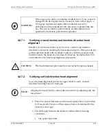
WARNING
:
If the air gap of a sensor containing a radioactive or X ray source is
changed from its original size (for example, from a 0.4 in gap to a
0.5 in gap), regulations require that a radiation survey be
performed and documented before the sensor is placed back into
use. This survey must be performed by an individual who is
specifically licensed to perform this operation.
4.2.7.1.
Verifying cross direction and machine direction head
alignment
Whether or not the heads line up in the cross, vertical, and machine
directions is tested by inserting the head alignment pins. If the pins do not
go through both heads with the heads located on both the scanner cable
and drive ends, the heads are not properly lined up. See Subsection 9.6.3
and Subsection 9.6.4 for head alignment procedures.
!
CAUTION
:
The head alignment pins must be removed before going onsheet.
4.2.7.2.
Verifying vertical direction head alignment
Leave the head alignment pins in the upper head to verify vertical-
direction head alignment or head gap.
i
N
OTE
:
Aligning the heads for the vertical direction involves adjusting only the
lower head.
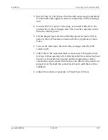
1.
Place two spacer bars between the heads (spacer bars are provided
by Honeywell). The size of these spacer bars is determined by the
system’s sensor gap.
2.
Check the gap between the heads for either of the following
conditions:
•
The spacer bars bind
P/N 6510020208
10/4/07
4-13
Summary of Contents for 4022
Page 1: ...Precision Platform 4022 Scanner System Manual 6510020208 ...
Page 2: ......
Page 3: ...Precision Platform 4022 Scanner October 2007 ...
Page 22: ......
Page 72: ......
Page 94: ......
Page 126: ......
Page 162: ......
Page 170: ......
Page 234: ......
Page 239: ...Glossary p n 6510020208 10 18 07 11 5 VIO Virtual Input Output ...

