background image

4

D

INITIAL INSTALLATION

PREPARATION

Before beginning the assembly of this product, ensure all parts are present. Compare all parts with the package contents list 

and hardware contents list. If any part is missing or damaged, do not attempt to assemble the product. 
Estimated assembly time: 2 hours
Tools required (not included): Electrical tape, Phillips Screwdriver, Safety Glasses, Step Ladder, and Wire Strippers.
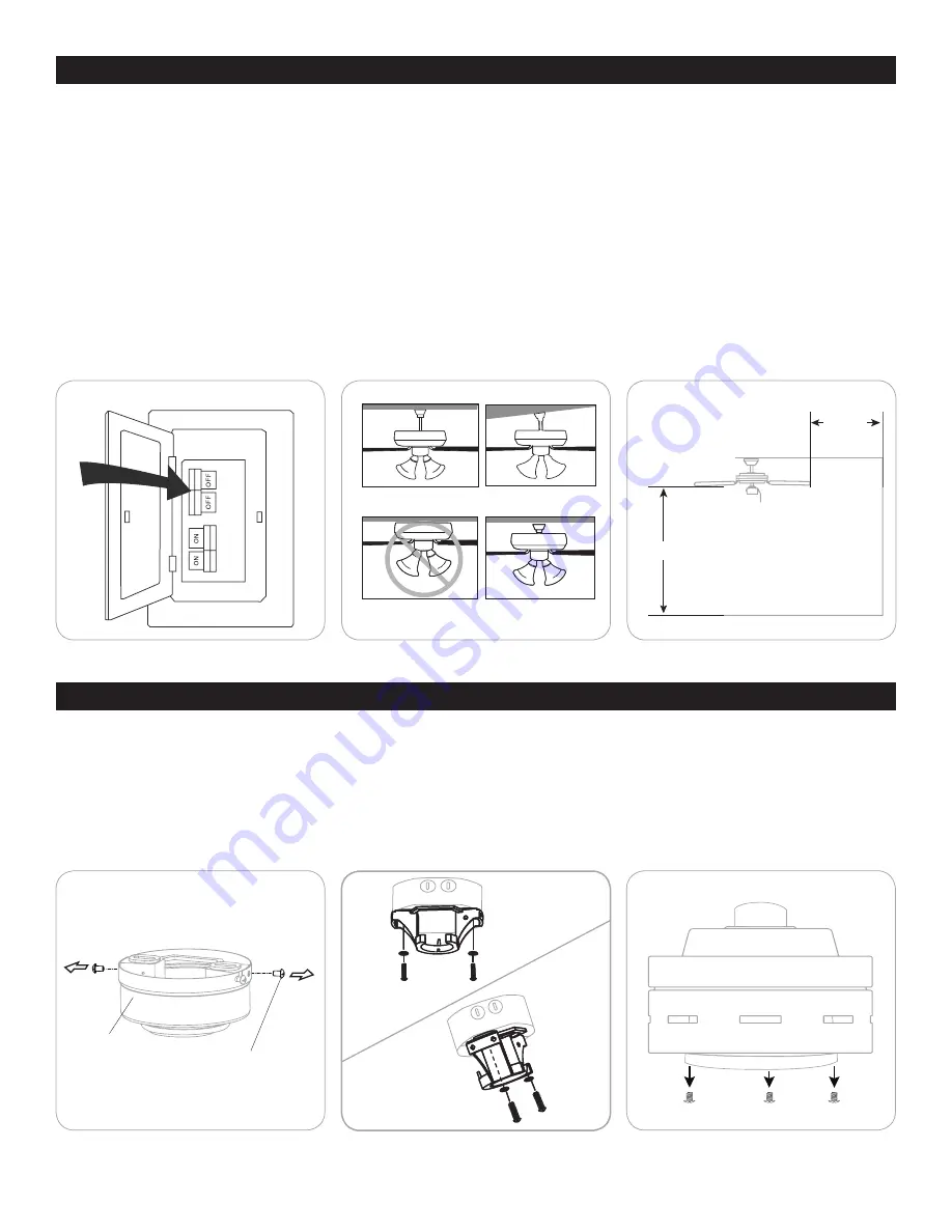
1. Turn off power to the fan at the breaker box and the wall switch (Figure 1.1). 

DANGER:

 Failure to disconnect the power supply 

prior to installation may result in serious injury or death.

2. Choose one of the following mounting options (Figure 1.2) :

    Standard Mount

 - best suited for ceilings 8 feet or higher. For very high ceilings, use a longer downrod (not included). 

Angle Mount 

- best suited for angled or vaulted ceilings. A longer downrod is sometimes necessary to ensure proper blade 

clearance. Ensure the ceiling angle is not steeper than 10 degrees. 

Flushmount Installation 

- not available for this model. 

Closemount Installation

 - best suited for ceilings 8 feet or lower. 

3. Choose a suitable location - Ensure the blades will be at least 30 inches from any obstructions. Also check the downrod 

length to ensure the blades will be at least 7 feet above the floor (Figure 1.3). 

1. Loosen all four mounting bracket screws and completely remove the two screws from the round holes in the canopy. Then 

remove mounting bracket from the canopy and save them for later (Figure 2.1). 

2. Install the mounting bracket to the outlet box (sold separately) using the screws and washers provided with the outlet box 

(Figure 2.2).

3. Remove the three fitter plate screws and the packing material from the motor assembly. Discard the orange packing material 

from the top and bottom of the motor assembly but save the three fitter plate screws for later (Figure 2.3). 

For CLOSEMOUNT INSTRUCTIONS, skip to page 6.

Figure 1.1

Figure 2.1

Figure 1.2

Standard and 

Closemount

Angle Mount

Light Pan Screw

Figure 2.2

Figure 1.3

Figure 2.3

Standard Mount

Flushmount

Angle Mount

Closemount


Mounting 

Bracket Screw

Canopy

7 ft. min.

30in. min.

Summary of Contents for 50608

Page 1: ...Xerxes Ceiling Fan User Guide Model 50608 50609 Home ...

Page 2: ...Blade Arm x 8 Blade x 8 Yoke Cover Set Screw x 2 Yoke Closemount Screw x 3 Motor Assembly Fitter Plate Fitter Plate Screw x 3 Light Kit Lens Cover Remote Kit Blade Balancing Kit Blade Screw x 24 Screw Cap x 24 Wire Connector x 1 Note Some extra hardware may be included The quantity listed above is the number required for installation ...

Page 3: ...larger than 12 gauge and or there is more than one house wire to connect to the two fan lead wires consult an electrician for the proper size wire connectors to use WARNING To reduce the risk of fire electric shock or personal injury do not bend the blade arms when installing them balancing the blades or cleaning the fan Do not insert objects between the rotating fan blades WARNING To reduce the r...

Page 4: ...egrees Flushmount Installation not available for this model Closemount Installation best suited for ceilings 8 feet or lower 3 Choose a suitable location Ensure the blades will be at least 30 inches from any obstructions Also check the downrod length to ensure the blades will be at least 7 feet above the floor Figure 1 3 1 Loosen all four mounting bracket screws and completely remove the two screw...

Page 5: ... downrod measure 8 inches of wire Cut off the excess wire using wire cutters not included Then strip 1 2 inch of insulation from the end of each wire strand Figure 3 4 5 Install the ball end of the downrod into the opening of the mounting bracket Figure 3 5 WARNING Failure to align the slot in the ball with the tap on the mounting bracket may cause the fan to fall which could result in injury or d...

Page 6: ...o connect household supply and fan wires according to the diagram Figure 5 1 and the following steps Connect the green wire from the downrod and mounting bracket to the Bare Green ground supply wire Note Closemount installation does not use the downrod so there will only be two Green wires to connect Connect the White wire with red label from the receiver to the White neutral supply wire Connect t...

Page 7: ... the single pin connector from the fitter plate to the single pin connector from the light kit Blue to Black and White to White Align the slotted holes in the light kit with the loosened screws in the fitter plate Turn light kit clockwise and replace the previously removed fitter plate screw Tighten all screws Figure 5 6 7 Attach the lens cover to the light kit by twisting the lens cover tightly i...

Page 8: ...l to dim or brighten the lights Non dimmable Bulbs Turns the lights on and off Note The dimmer function does not work with CFL bulbs F D CFL Switch Switch should be set to D to correspond with the included LED bulbs which will enable the dimming function Flip to CFL if you change to non dimmable bulbs Figure 6 1 2 Use the reverse switch located on the top of the motor assembly to optimize your fan...

Page 9: ...ttons on the remote at the same time for 5 seconds The LED indicator will flash 3 times signaling a successful synchronization Once complete the fan will start on the low speed with the light if applicable off 2 Insert new 12V battery in battery compartment of the remote 3 If there are several remote fans in close proximity turn the power off to those fans and re sync the fan 1 Check and tighten a...

Page 10: ...itation of incidental or consequential damages so this limitation may not apply to you If the original purchaser ceases to own the fan this warranty is voided Should the purchaser encounter a problem with your fan related to defects in workmanship or materials within the warranty period associated with the defective part HKC agrees to replace the defective part without charge or at its option to r...

Reviews: