


4 - 38
MAN0443.P65 Issue 13 Aug 04
5701 Control System
05701-M-5001 A02279
CHAPTER 4 - INSTALLATION INSTRUCTIONS
LK3
LK1
LK12
LK9
LK6
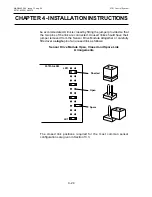
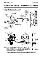
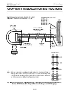
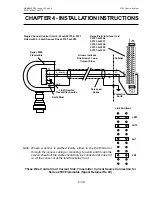
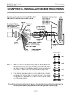
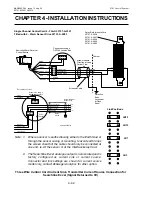
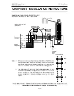
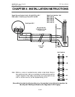
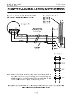
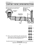
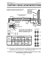
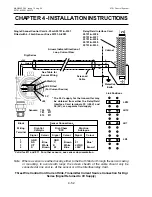
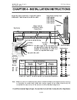
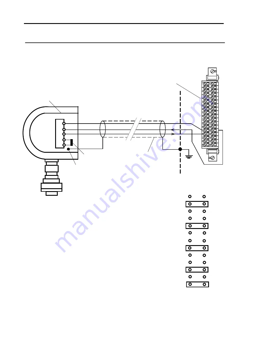
Three Wire Control Card Current Source, Transmitter Current Sink Connection for
Series 2000 Flammable (Signal Returned to Regulated 23V Supply)
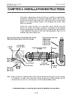
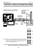
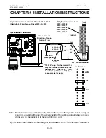
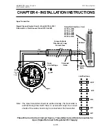
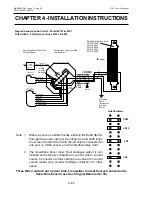
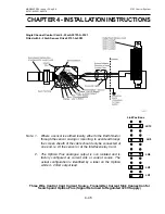
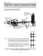
Note: Where a sensor is earthed locally, either to the Earth Stud or
through the sensor casing or mounting, to avoid earth loops the
screen sheath of the cable should only be connected at one end.
ie. At the sensor or at the Interface/relay Card.
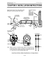
Link Positions
Single Channel Control Card 4 - 20mA 05701-A-0301
Fitted with 4 - 20mA Sensor Drive 05701-A-0283
Relay/Field Interface Card
05701-A-0326
05701-A-0327
05701-A-0328
05701-A-0329
05701-A-0330
Screened
Cable
Arrows Indicate
Direction of Loop
Current Flow
S
01
NS
Earth Stud
+24V
4 - 20mA (+)
0V
GND
Series 2000
Flammable
11
3
9
4
5
Link fitted for
Transmitter Sink
Cabinet
Protective
Earth
28
27
29


