1-5
MAN0448_Issue 13_01-2010
5704 Control System
005704-M-5001 A03249
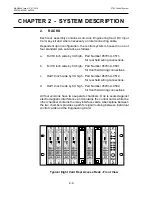
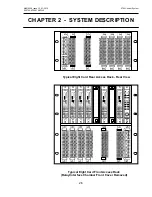
In a system where the field wiring is required to be connected to the rear
of the system, the rack is centrally divided into front and rear sections
by a printed circuit board backplane which provides common signal
routeing between individual Four Channel Control Cards. The control
cards are fitted at the front of the rack while Quad Relay Interface Cards
are fitted directly behind the associated Four Channel Control Card at
the rear of the rack. The control cards and their respective interface
cards are interconnected by a plug and socket arrangement.
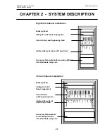
In a system where the field wiring is required to be connected to the front
of a system, the Four Channel Control Cards and Quad Relay Interface
Cards are mounted one above the other in a 6U rack. The backplane
printed circuit board still provides the common signal routeing between
the individual Four Channel Control Cards, but short cables at the rear
of the cards connect each control card to their respective Quad Relay
Interface Card.
Simple calibration and checking of the system is carried out using push
buttons on the Engineering Card fitted in each rack. More complex
configuration can be carried out using the RS232 link between the
Engineering Card and an external IBM compatible personal computer
running the engineering interface software.
When a Relay Interface Assembly is used, the resultant four channel
control assembly then takes up two card slots.
A mixture of 5704 and 5701 Control Cards may be fitted in the same
System 57 rack.
The 5704 Control System is shown in Figure 1.
CHAPTER 1 - SySTEM CONCEPT
Summary of Contents for 5704
Page 1: ...System 57 5704 Control System Operating Instructions ...
Page 4: ...4 MAN0448_Issue 13_01 2010 5704 Control System 005704 M 5001 A03249 ...
Page 6: ...6 MAN0448_Issue 13_01 2010 5704 Control System 005704 M 5001 A03249 User Notes ...
Page 14: ...1 8 MAN0448_Issue 13_01 2010 5704 Control System 005704 M 5001 A03249 User Notes ...


