7-14
MAN0448_Issue 13_01-2010
5704 Control System
005704-M-5001 A03249
CHAPTER 7 - ENGINEER'S OPERATING
INSTRUCTIONS
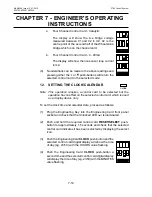
a. Four Channel Control Card - Catalytic
The display will show the live bridge voltage
measured between 01 and 02 in mV. 02 is the
centre point of the second half of the Wheatstone
bridge which is on the channel card.
b. Four Channel Control Card - 4 - 20mA
The display will show the live sensor loop current
in mA.
(4) No alterations can be made to the above readings and
pressing either the or push-buttons will return the
selected control card to the selected mode.
12. SETTING THE ClOCK/CAlENDAR
Note: This operation requires a control card to be selected but the
operation has no effect on the selected control card, which is used
as a display device only.
To set the clock time and calendar date, proceed as follows:
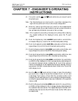
(1) Plug the Engineering Key into the Engineering Card front panel
socket and check that the Unlocked LED ( ) is illuminated.
(2) Push and hold the required control card
RESET/SElECT
push-
button for approximately 1.5 seconds and check that the selected
control card indicates it has been selected by displaying the select
icon.
(3) Push the Engineering Card
ClOCK
push-button and the
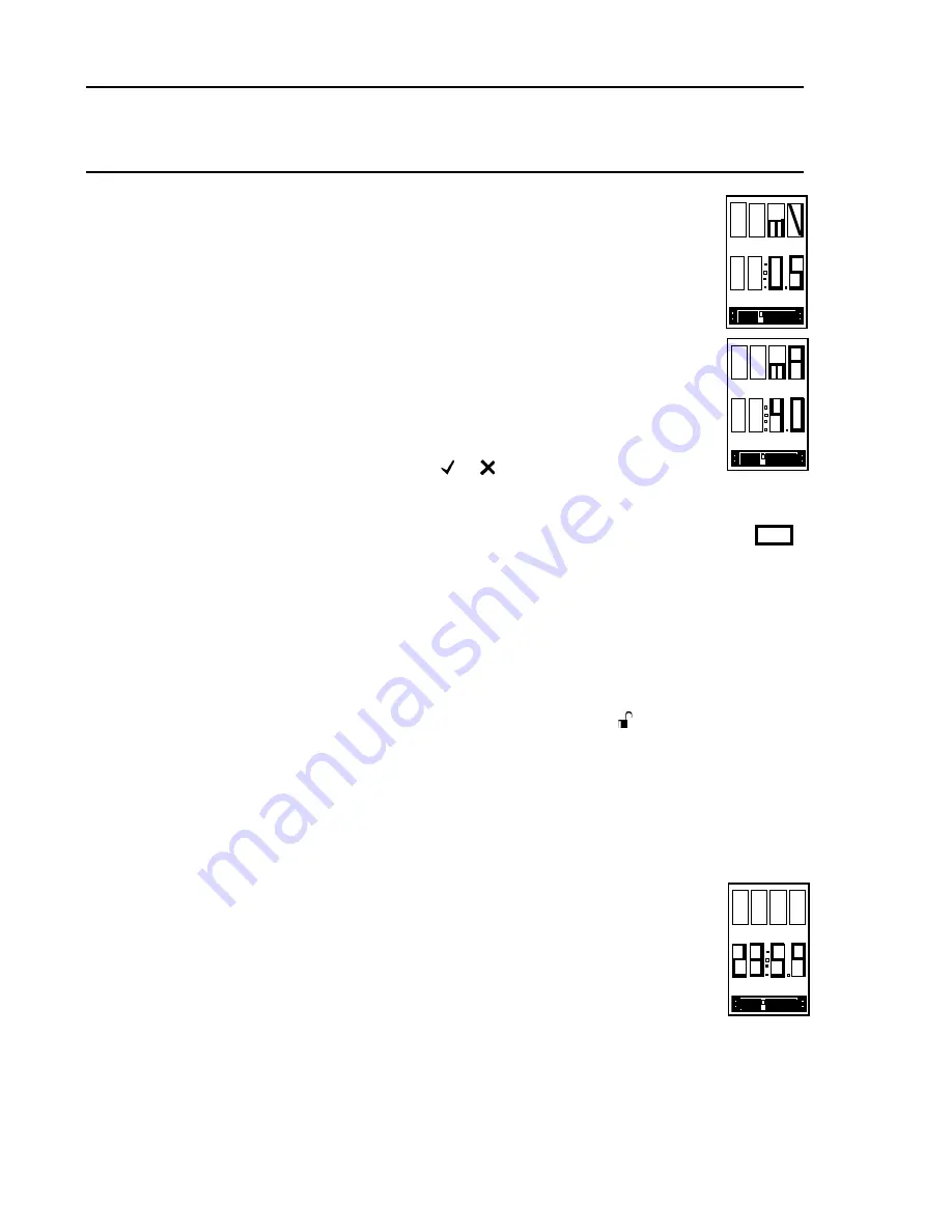
selected control card digital display will show the time
of day (eg. 23:59) with the HOURS value flashing.
(4) Push the Engineering Card
ClOCK
push-button a
second time and the selected control card digital display
will display the time of day (eg. 23:59) with the MINUTES
value flashing.
ClOCK
Summary of Contents for 5704
Page 1: ...System 57 5704 Control System Operating Instructions ...
Page 4: ...4 MAN0448_Issue 13_01 2010 5704 Control System 005704 M 5001 A03249 ...
Page 6: ...6 MAN0448_Issue 13_01 2010 5704 Control System 005704 M 5001 A03249 User Notes ...
Page 14: ...1 8 MAN0448_Issue 13_01 2010 5704 Control System 005704 M 5001 A03249 User Notes ...


