background image


- 2 -


Contents 


1. General ....................................................................................................... 3


1.1 Introduction to Actuator ...................................................................................................... 3


1.2 Actuator Structure ................................................................................................................ 3


2. Storage ....................................................................................................... 4


3. Operation ................................................................................................... 5


3.1 Inspections before Operation ............................................................................................. 5


4. Maintenance and Repair ........................................................................... 6


4.1 Valve Disassembly ............................................................................................................... 6


4.2 Disassembly and Assembly of Actuator ............................................................................ 7


4.2.1 Disassembly (See Fig 4.1) ................................................................................................7


4.2.2 Assembly (See Fig 4.1) ....................................................................................................7


5. Preventive Maintenance and Troubleshooting ....................................... 9


5.1 Troubleshooting ................................................................................................................... 9


6. Dimension Table ...................................................................................... 10


6.1 Double Acting Type ............................................................................................................ 10


6.2 Spring Return Acting Type ................................................................................................ 12


Summary of Contents for 6200 Series

Page 1: ...Revision 1 1 Series 6200 Cylinder Actuator 70 17 41 06 EN INSTALLATION OPERATION MAINTENANCE MANUAL ...

Page 2: ... before Operation 5 4 Maintenance and Repair 6 4 1 Valve Disassembly 6 4 2 Disassembly and Assembly of Actuator 7 4 2 1 Disassembly See Fig 4 1 7 4 2 2 Assembly See Fig 4 1 7 5 Preventive Maintenance and Troubleshooting 9 5 1 Troubleshooting 9 6 Dimension Table 10 6 1 Double Acting Type 10 6 2 Spring Return Acting Type 12 ...

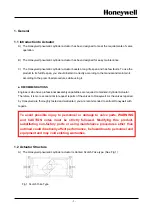
Page 3: ...nal assembly capabilities are required to maintain Cylinder Actuator Therefore it is more economical to request repairs of the valves to Honeywell As the valves repaired by Honeywell are thoroughly tested and warranted you are recommended to entrust Honeywell with repairs 1 2 Actuator Structure A The Honeywell pneumatic cylinder actuator is Canted Scotch Yoke type See Fig 1 Fig 1 Scotch Yoke Type ...

Page 4: ...ge area must be protected from flooding C Operate the elastomer O ring type of air pressure type actuator at least once every six months to prevent their functional degeneration Operate it to the full stroke even under general operation conditions at least three times a month Valve Handling Method During Transportation WARNING Do not hold it up or drag it using the stopper part when moving it The ...

Page 5: ...pecification 6 0 kgf cm2 WARINING Remove air pressure from the actuator before using the manual hand wheel If you use the hand wheel without removing air pressure it may not work normally and its weak part may get damaged by overstrain If the manual hand wheel is not at the neutral position during control operation it may not work normally and its weak part may get damaged If you use a pressure hi...

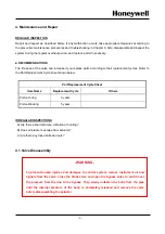
Page 6: ...e sheet shown below Part Replacement Cycle Sheet Item Name Replacement Cycle Others Piston O ring 3 years Piston Wearing 5 years IRREGULAR INSPECTIONS A Are there abnormal noise vibration or hunting B Does air pressure escape from actuator C Are there any loose bolts and nuts 4 1 Valve Disassembly WARNING To prevent human injuries and damages to control system remove instrument air and signals fro...

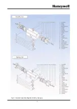
Page 7: ...eplace 2 tension bolts and remove the others Slowly remove the remaining 2 bolts while keeping the actuator spring without load Remove the cylinder cover Remove the pipe and then remove the piston from the spindle Remove the spindle from the arm while taking care not to damage the surface of the spindle and then pull out the arm from the housing Check the O ring and wearing and replace them if nec...

Page 8: ... 8 Fig 4 1 Actuator Assembly Diagram Scotch yoke type ...

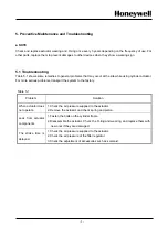
Page 9: ...or more serious problems transport the system to the factory Table 5 1 Problem Solution When actuator does not operate 1 Check the air pressure supplied to the actuator 2 Remove the actuator and check spring and piston Leak from actuator components 1 Fasten the bolts on the cylinder frame 2 Disassemble the actuator Check the O ring and wearing and replace them with new ones if they are damaged The...

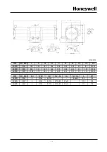
Page 10: ...10 443 136 68 68 164 144 20 22 AC14D F10 F12 486 158 79 79 180 160 20 22 AC16D F10 F12 560 178 86 92 210 190 20 26 F14 SIZE ISO BASE PCDØ CH Dp N M AC06D F05 F07 Ø50 Ø70 14x14 17 4 M6 M8 AC08D F07 Ø70 17x17 19 4 M8 AC10D F07 F10 Ø70 Ø102 22x22 26 4 M8 M10 AC12D F07 F10 Ø70 Ø102 22x22 26 4 M8 M10 AC14D F10 F12 Ø102 Ø125 27x27 30 4 M10 M12 AC16D F10 F12 Ø102 Ø125 27x27 30 4 M10 M12 F14 Ø140 36x36 4 ...

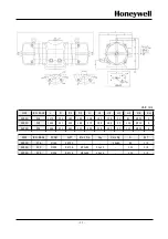
Page 11: ...38 20 81 Ø130 AC25D F25 928 411 225 186 373 188 165 20 100 Ø200 AC30D F25 1098 472 260 212 422 212 190 20 110 Ø200 SIZE ISO BASE RH PCDØ N M Ød x Dp Key CH x Dp A RCT AC20D F16 3 Ø165 4 M20 46x65 80 1 4 AC25D F25 4 Ø254 8 M16 Ø75x85 20x12 130 3 8 AC30D F25 4 Ø254 8 M16 Ø90x85 25x14 130 3 8 ...

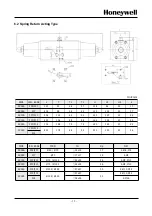
Page 12: ...F07 F10 640 136 68 68 164 144 20 22 AC14S F10 F12 716 158 79 79 180 160 20 22 F10 F12 F14 20 26 AC16S 850 178 86 92 210 190 SIZE ISO BASE PCDØ CH Dp N M AC06S F05 F07 Ø50 Ø70 14x14 17 4 M6 M8 AC08S F07 Ø70 17x17 19 4 M8 AC10S F07 F10 Ø70 Ø102 22x22 26 4 M8 M10 AC12S F07 F10 Ø70 Ø102 22x22 26 4 M8 M10 AC14S F10 F12 Ø102 Ø125 27x27 30 4 M10 M12 F10 F12 27x27 4 M10 M12 F14 36x36 4 M16 AC16S Ø102 Ø125...

Page 13: ... 138 20 81 Ø130 3 AC25S F25 1424 411 225 186 373 188 165 20 100 Ø200 4 AC30S F25 1664 472 260 212 422 212 190 20 110 Ø200 4 SIZE ISO BASE PCDØ N M Ød x Dp Key CH x Dp A Rc T AC20S F16 Ø165 4 M20 46x65 80 1 4 AC25S F25 Ø254 8 M16 Ø75x85 20x12 130 3 8 AC30S F25 Ø254 8 M16 Ø90x85 25x14 130 3 8 ...

Page 14: ...ocess Solutions TAC hfs tac support honeywell com Australia Honeywell Limited Phone 61 7 3846 1255 FAX 61 7 3840 6481 Toll Free 1300 36 39 36 Toll Free Fax 1300 36 04 70 China PRC Shanghai Honeywell China Inc Phone 86 21 5257 4568 Fax 86 21 6237 2826 Singapore Honeywell Pte Ltd Phone 65 6580 3278 Fax 65 6445 3033 South Korea Honeywell Korea Co Ltd Phone 822 799 6114 Fax 822 792 9015 ...

Page 15: ...es Visit www honeywellprocess com Or contact your Honeywell Account Manager Process Solutions Honeywell 1250 W Sam Houston Pkwy S Houston TX 77042 Honeywell Control Systems Ltd Honeywell House Skimped Hill Lane Bracknell England RG12 1EB Shanghai City Center 100 Jungi Road Shanghai China 20061 www honeywellprocess com Honeywell ...

Reviews: