background image

Section 3:  Programming Overview 

3–5 

Zone Type 

Description 

24 Hour Carbon 
Monoxide 
Monitor 

The internal sounder output will pulse when this zone type is alarmed.  

Always active and cannot be bypassed. 

Type 20 
Arm-Stay  
(BR only) 

Arms the system in Stay mode when the zone is activated.  

Pushbutton units send the user number to the central station when 
arming or disarming. 

User number for button must be assigned. 

Type 21 
Arm-Away  
(BR only) 

Arms the system in Away mode when the zone is activated.  

Pushbutton units send the user number to the central station when 
arming or disarming. 

User number for button must be assigned. 

Type 22 
Disarm  
(BR only) 

Disarms the system when the zone is activated. 

User number for button must be assigned. 

Type 23 
No Alarm 
Response 

Can be used on a zone when an X-10 powerline carrier device action is 
desired, but with no accompanying alarm (e.g., lobby door access).   

The system can still be armed when these zone types are in a faulted 
condition.   

Type 24 
Silent Burglary 

Usually assigned to all sensors or contacts on exterior doors and windows 
where internal sounder is NOT desired. 

Provides an instant alarm, with NO audible indication at any keypad or 
external sounder, if the zone is faulted when the system is armed in the 
Away, Stay, Instant, or Maximum modes.  

A report is sent to the central station. 

Types 90-91 
Configurable 

Allows for various custom responses. Options include response to 
entry/exit delays, zone faults, types of alarm/trouble sounding, dial delay, 
and unique Contact ID report codes.   

UL installations: Zone Types 90 - 91 may not be used as fire or burglar 
alarm zones on fire or UL burglar alarm installations. 

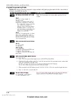
Mechanics of Programming 


To program the system from a keypad: 

You must use an Installer Keypad 6160 or 6139. 
System must be disarmed. 

Installer Keypad Functions 

A Standard 6139 or 6160 alpha keypad is used to program, test, and diagnose the control and 
is referred to as the Installer Keypad.  The Installer Keypad is automatically sensed when 
connected and is powered by the control.  The Installer Keypad is connected to the installer 
keypad programming connector shown in Figure 1.  Address 16 is reserved for the Installer 
keypad.   

NOTE:

  The Installer Keypad keys function are dependent on program mode selected, Data 

Field Programming, or Quick Mode Programming.   

www.PDF-Zoo.com

firealarmresources.com

Summary of Contents for ADEMCO LYNX XL Series

Page 1: ...rity System Security System Security System Security System LXL LXL LXL LXL 1010 1010 1010 1010 Installation and Setup Guide Installation and Setup Guide Installation and Setup Guide Installation and Setup Guide BETA DRAFT COPY 8 23 04 K9349 1 8 04 Rev A www PDF Zoo com firealarmresources com ...

Page 2: ...ide may not wake up the sleeper if the door is closed DINING KITCHEN BEDROOM BEDROOM BEDROOM BEDROOM LIVING ROOM BEDROOM BDRM BDRM DINING LIVING ROOM TV ROOM KITCHEN BEDROOM BEDROOM TO BR LVNG RM BASEMENT KTCHN CLOSED DOOR GARAGE Smoke Detectors for Minimum Protection Smoke Detectors for Additional Protection Heat Activated Detectors floor_plan 001 V0 Install a smoke detector inside bedrooms where...

Page 3: ...ID 2 4 Add Primary Sub ID Account Number 2 4 SEC PHONE 2 5 Add Secondary Phone Number 2 5 SEC SUB ID 2 5 Add Secondary Sub ID Account Number 2 5 ADD SENSORS 2 5 Add A Door Sensor 2 5 To Add a Window Motion Fire Glass Break or Shock Sensor 2 6 Add Emergency Sensor 2 6 Add Keyfob 2 6 DELETE SENSORS 2 7 Delete Sensors 2 7 EXPERT MODE 2 7 Enter Expert Programming Mode 2 7 5 Completing Programming 2 7 ...

Page 4: ...Output Definition Components 7 2 Zone Lists 81 8 1 About Zone Lists 81 menu Mode 8 1 Alpha Descriptor Programming 82 Menu Mode 9 1 About Descriptor Programming 9 1 Creating Schedules 10 1 System Communication 11 1 LXL 1010 and Dialer Communication with Central Station 11 1 System Operation 12 1 LED Indications 12 1 System Security Codes 12 1 Keypad Functions 12 2 Voice Keypads 12 2 Keypad Commands...

Page 5: ...elephone wiring Refer to Figure 1 for the LXL 1010 internal overview QM 041 V0 SECURITY SYSTEM CONTROL STATUS LEDs 3 RJ31 TELEPHONE JACK ANTENNA BATTERY SOUNDER COVER TAMPER INSTALLER KEYPAD PROGRAMMING CONNECTOR BATTERY CONNECTOR ANTENNA SOUNDER JUMPER RF LED AUX TELEPHONE JACK RJ11 Figure 1 LXL 1010 Internal Overview Capabilities Zones Supports up to 32 wireless transmitter zones 5800 series zon...

Page 6: ...839 Alpha RF Keypads and unlimited 5828 Fixed RF Keypads or 5828V Fixed RF Voice Keypads Function keys will not work as set in 57 Supports 5800 series transmitters Powerline Carrier Devices X 10 type For programming the control during installation supports either a 6160 or 6139 Alpha keypad Installer Keypad System Features Tamper Protection The control is tampered protected An alarm will sound if ...

Page 7: ...the subsequent keypad s if used uses address 02 03 04 05 06 07 respectively The 5828 series keypads use the house ID Relays have two programming menu modes Use 79 Menu mode to map device output numbers Use 80 Menu mode to define the output functions see Output Device Programming section This system supports programmable function keys Use 57 Menu mode to define the function keys see Function Key Pr...

Page 8: ...LXL 1010 Installation and Setup Guide 1 4 www PDF Zoo com firealarmresources com ...

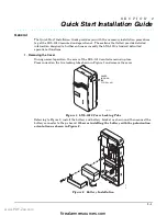
Page 9: ...moving the Cover During normal operation the cover of the LXL 1010 control remains in place Press inward on the two locking tabs shown in Figure 1 and remove the cover QM 023 V0 COVER LOCKING TAB TYPICAL L R QuikMateR Figure 1 LXL 1010 Cover Locking Tabs Referring to Figure 2 install the battery and battery bracket as shown and then connect the battery connector to the pc board Observe installing ...

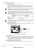
Page 10: ...ances from Electrical Equipment EQUIPMENT DISTANCE PIR 10 ft FM radio or TV antenna 25 ft Other devices 10 ft minimum The LXL 1010 is intended for indoor installation only Mounting outdoors will cause system failure and may present a shock hazard 3 Connecting the Installer Keypad Connect the Installer Keypad to the Programming Connector as shown in Figure 3 and then set the Installer Keypad addres...

Page 11: ...ode the programming keypad will display Add Sensors 3 Press the 6 or 3 key to scroll through the options Add Sensors Sec Sub ID Delete Sensors Select Defaults Pri Phone Program LRR Pri Sub ID LRR Registration Sec Phone Expert Mode 4 Press the SELECT function key to select the option for editing Program each option as follows If you make a mistake editing an option you must exit the option and then...

Page 12: ...displayed If the field is selected for editing the data in that field will be deleted The field can be left blank by pressing the ADD key Enter new data and then press the ADD key Add Primary Phone Number Scroll to Pri Phone Press SELECT Enter first central station phone number up to 20 digits Press ADD Scroll to next option or ESC QM 016 V0 PRI SUB ID Scroll to the Pri Sub Id option to enter the ...

Page 13: ... number fields the existing data is displayed If the field is selected for editing the data in that field will be deleted The field can be left blank by pressing the ADD key Enter new data and then press the ADD key All four digits of the Central Station Account number must be entered If ten digit format is being used all ten digits must be entered Add Secondary Sub ID Account Number Press SELECT ...

Page 14: ...tivate transmitter twice or enter S N manually Press ADD Scroll to next option or ESC 5 Pendant Type Medical Fire Silent Police Police Add Keyfob When adding wireless keys wait 5 seconds between transmissions Scroll to Add Sensors Press SELECT Press SELECT Scroll to Add Keyfob Press SELECT QM 015 V1 Activate transmitter twice or enter S N manually Press ADD Scroll to next option or ESC Scroll to d...

Page 15: ...xpert Mode is selected from QUICK MODE programming you will be locked out of Quick Mode programming You should choose this entry only if you desire to restrict re entry into Data Field Programming via 98 exit Enter Expert Programming Mode Once you have entered the Expert Programming Mode the ESC key cannot be used to return to Quick Mode Programming mode Scroll to Expert programming mode Press SEL...

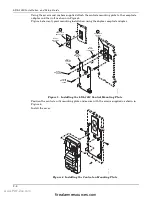
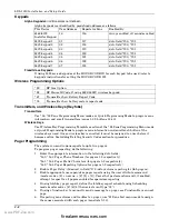
Page 16: ...LL ANCHOR 5 SUPPLIED WALL MOUNTING SCREWS 4 TYP TAMPER MOUNTING SCREW INSTALL MOUNTING PLATE REMOVE RECEPTACLE COVER PLATE OUTLET MOUNTING SCREW 3 1 OUTLET MOUNTING SCREW RECEPTACLE ADAPTER PLATE 2 Figure 5 Installing the LXL 1010 Control Mounting Plate Position the control on it s mounting plate and secure with the screws supplied as shown in Figure 6 Install the cover QM 010 V1 Figure 6 Installi...

Page 17: ...means of connecting an additional telephone RJ31X 1 2 3 4 5 6 7 8 RING TIP INCOMING PHONE LINE TO PREMISES PHONES GREEN RED GREY BROWN RING TIP DIRECT CONNECT CORD AUX JACK RJ11 RJ31 JACK QM 024 V0 R DETAIL A SIDE VIEW SEE DETAIL A Figure 7 Phone Line and Handset Wiring 7 Test the System Refer to Testing LXL 1010 Section 13 and perform a System Test www PDF Zoo com firealarmresources com ...

Page 18: ...LXL 1010 Installation and Setup Guide 2 10 www PDF Zoo com firealarmresources com ...

Page 19: ...ion that can be used to modify defaulted programming options 56 Zone Programming Assign zone characteristics report codes alpha descriptors and serial numbers for 5800 RF transmitters 57 Function Key Programming Programs each 5839 used four alphabet function keys to perform one of several system operations 58 Zone Programming Assign zone attributes similar to 56 mode but provides a faster programm...

Page 20: ...on of the 58 Zone Programming Menu mode or Quick Programming Mode to program zone information and enroll each button of the wireless keys used Once a wireless key is enrolled it must be assigned to a user before it becomes active See Adding Deleting Security Codes section for procedure Pager Programming The system can send various reports to up to two pagers To program pager reporting do the follo...

Page 21: ...sing 4 1 1 2 Installer code followed by 8 8 8 on the Installers Keypad after the initial startup delay busy standby is terminated or expires Zone Type Definitions A zone type must be assigned to each zone Zone type defines the way in which the system responds to faults in that zone Quick Mode Programming automatically assigns zone types based on the sensor selected When using Data Field Programmin...

Page 22: ...liary Alarm Assign to a zone containing an emergency button or to a zone containing monitoring devices such as water or temperature sensors Sends a report to the central station and provides an alarm sound at the keypad internal sounder and an audible external alarm Type 09 Supervised Fire Provides a fire alarm when detector is faulted and a trouble condition when the cover is removed A fire alarm...

Page 23: ... internal sounder is NOT desired Provides an instant alarm with NO audible indication at any keypad or external sounder if the zone is faulted when the system is armed in the Away Stay Instant or Maximum modes A report is sent to the central station Types 90 91 Configurable Allows for various custom responses Options include response to entry exit delays zone faults types of alarm trouble sounding...

Page 24: ...s Interactive Mode No for example 56 while in Program Mode The Alpha display keypad will display the first of a series of prompts requesting entries After making the appropriate entry press the key to accept the entry and continue to the next prompt Loading Factory Defaults Initializing for Download Task Procedure To Load Default Entries Press 97 while in Program Mode and enter the desired default...

Page 25: ...ays needed to disarm the system 22 RF Jam Option 0 no RF jam detection 1 send RF jam report If enabled a report is sent if the system detects an RF jamming signal UL installations must be 1 if wireless devices are used 23 Quick Forced Bypass 0 no quick bypass 1 allow quick bypass code 6 All zones bypassed by this function will be displayed after the bypass is initiated UL installations must be 0 n...

Page 26: ...lations minimum exit delay is 45 seconds 35 Entry Delay 1 00 96 0 96 seconds 97 120 seconds 98 180 seconds 99 240 seconds Upon entering the system must be disarmed before the time entered expires otherwise it sounds an alarm UL installations For UL Residential Burglary Alarm installations must be set for a maximum of 30 seconds entry delay plus dial delay should not exceed 1 min For UL Commercial ...

Page 27: ...er digits 0 9 11 for B 12 for C 13 for D 14 for E 15 for F To clear entries from field press 44 47 Phone System Select If Central Station Receiver is not on WATS line 0 Pulse Dial 1 Tone Dial If Central Station Receiver is on WATS line 2 Pulse Dial 3 Tone Dial Select the type of telephone service 48 Report Format Primary Secondary 0 3 1 4 1 ADEMCO L S STANDARD 1 3 1 4 1 RADIONICS STANDARD 2 4 2 AD...

Page 28: ... to the Central Station office Entries in the second boxes are ignored An entry of 0 in the first box disables the report UL installations Program fields 59 76 as required by the applicable UL Standards shown in each field FIELD TITLE and DATA ENTRIES EXPLANATION 59 Exit Error Report Code 0 no report 1 F see description above After arming the system zones remaining open after exit delay expires ca...

Page 29: ... are used 68 Cancel Report Code 0 no report 1 F see description above 59 This is sent upon disarming of the system after an alarm condition was reported 70 Alarm Restore Report Code 0 no report 1 F see description above 59 Sent when an alarm zone is restored to its non faulted condition UL Required for UL commercial burglar alarm installations and required for residential fire alarm installations ...

Page 30: ... 9 5 min 15 15 min 4 90 secs 10 6 min 5 2 min 11 7 min Sets the maximum amount of time in which two cross zones must be tripped in an armed system to send an alarm message to the Central Station If only one cross zone is tripped during this time a trouble message CID code 380 for that zone is sent to the Central Station Assign cross zone pairs in zone list 4 This option not for use in UL installat...

Page 31: ... TITLE and DATA ENTRIES EXPLANATION 92 Phone Line Monitor Enable Entry 1 Timeout 0 disabled 1 15 1 minute to 15 minutes respectively 2 2 min 3 3 min etc 10 10 min 11 11 min 12 12 min 13 13 min 14 14 min 15 15 min Entry 2 Display Sound 0 keypad display only when phone line is faulted 1 keypad display plus keypad trouble sound when line is faulted No automatic timeout 2 Same as 1 plus programmed out...

Page 32: ... entry by Installer Code 8 0 0 or by Pressing and at the same time within 50 seconds of power up Pager Programming Fields FIELD TITLE and DATA ENTRIES EXPLANATION 160 Pager 1 Phone No Enter up to 20 digits If you enter fewer than 20 digits exit by pressing and next field number To clear entries from this field press 160 161 Pager 1 Characters Enter up to 16 characters Up to 16 optional characters ...

Page 33: ...e dialer attempts to dial the pager NOTE The delay does not reset for new alarms occurring while an existing pager delay is in progress This delay is for ALL pagers in the system Miscellaneous System Fields FIELD TITLE and DATA ENTRIES EXPLANATION 177 Device Duration 1 2 0 15 secs 6 2 1 2 min 12 8 min 1 30 secs 7 3 min 13 10 min 2 45 secs 8 4 min 14 12 min 3 60 secs 9 5 min 15 15 min 4 90 secs 10 ...

Page 34: ...f the window is later closed it will be protected opening the window again causes an alarm Bypass Disarmed entry 4 Zones set for this option can be bypassed only while the system is disarmed Bypass Armed entry 4 Zones set for this option can be bypassed when the system is armed or disarmed Dial Delay entry 6 Alarms on zones set for this option participate in dial delay central station reporting if...

Page 35: ...DIGIT 7 DIGIT 8 Display Faults Use Entry Delay 1 2 Use Exit Delay Respond as Interior Type 0 always 1 when disarmed 3 never 0 no 1 delay 1 2 delay 2 0 no 4 use exit delay 0 no 8 yes see note 2 Digit 7 fault display Digit 8 entry delay 1 entry delay 2 exit delay interior zone type DIGIT 9 DIGIT 10 Alarm Sounds Use Alarm Timeout Respond as Fire Zone Trouble Sounds Chime when Chime Mode On 0 none 1 s...

Page 36: ... of option selected 190 SITE ID 5839 KEYPAD OPTIONS Enable 0 without 5839 s 1 with 5839 s Sound Option 0 no suppression 1 suppress arm disarm and E E beeps 2 suppress chime beeps only 3 suppress arm disarm E E beeps and chime beeps 191 SITE ID 5839 ENROLLMENT MODE To enroll the Site ID 1 Press 191 on the programming keypad to enter the Site ID Enrollment Mode 2 With Site ID Enrollment Mode selecte...

Page 37: ...ial number of wireless transmitter zones Start Zone Programming mode by pressing 56 while in Data Programming mode The following prompts are displayed PROMPT VALID ENTRIES EXPLANATION SET TO CONFIRM 0 NO 1 YES Set to Confirm 0 no 1 yes If 1 Yes is entered you will be prompted to confirm each transmitter after entering the serial and loop numbers at the XMIT TO CONFIRM prompt later in this procedur...

Page 38: ...rs can be enrolled as one of the following types Type Description RF Sends periodic check in signals as well as Supervised RF fault restore and low battery signals The transmitter must stay within receiver s range UR Sends all the signals that the RF type Unsupervised RF does but the control does not supervise the check in signals The transmitter may therefore be carried off premises BR Unsupervis...

Page 39: ... been enrolled Press to accept the zone information and continue PROGRAM ALPHA 0 NO 1 YES 0 Alpha Descriptors 0 no 1 yes to continue If you want to program descriptors for zones now enter 1 Yes and refer to the Alpha Descriptor Programming section for available descriptors ENTER ZN NUM 00 QUIT 11 Next Zone Number 00 quit to continue If 0 No was entered above the system will return you to the ENTER...

Page 40: ... move the cursor within the screen Use the C key to copy the previous zones attributes Press to save the programming and continue to the serial number loop number prompt If needed you can press the key to back up without saving If RF BR or UR is entered a prompt for Serial and Loop number will be displayed as follows 10 INPUT S N L AXXX XXX Serial number S N serial number L loop number to continue...

Page 41: ...emplates 4 6 5804BD templates to continue 1 Enter Template number 1 6 from next page See the defaults provided for each template in the chart that follows these procedures 2 Select from templates Press to display template 1 shown selected NOTE If necessary press to back up and re enter template number 3 Press if you want to return to zone attributes screen L 01 02 03 04 T 23 22 21 23 Template Disp...

Page 42: ...y NOTE Following the successful enrollment of each wireless device remove ONE of the serial number labels from the device and affix it in the appropriate column on the ENROLLED TRANSMITTERS worksheet of the Programming Form then enter the other information zone number zone type loop number etc relevant to that device Wireless Key Predefined Default Templates YOU MUST PROGRAM THIS BUTTON LOOP 4 LOO...

Page 43: ... 6 5 4 9 8 7 0 READY INSTANT MAX OFF CODE AWAY TEST CHECK STAY BYPASS A B C D keypad_keys 00 001 V0 Key A Func Zone 95 00 Define Key Function 00 12 see list to right to continue Returns to key number prompt with the next function key letter displayed Default A 03 arm AWAY B 04 arm STAY C 09 Macro 1 D 08 communication test Enter the desired function for this key 00 to 12 from the options listed 00 ...

Page 44: ...LXL 1010 Installation and Setup Guide 6 2 www PDF Zoo com firealarmresources com ...

Page 45: ...tput numbers and map them to device addresses NOTE You must map output devices using 79 Menu Mode before you can use 80 menu Mode 2 Use 80 Menu Mode to create output definitions which control the output devices 79 Menu Mode Output Device Mapping Use this menu to assign Powerline Carrier unit numbers The following table shows how these outputs are identified Output Identification This output is ide...

Page 46: ... This means that if more than one output device needs to perform this particular function you need to define another output function number with the same attributes but assign the appropriate output number i e output devices can be assigned more than one function number but each function number can only be assigned a single output number For example if you want to pulse a strobe light upon fire al...

Page 47: ...skip to the Output Action prompt B 01 Enter Zn type Perimeter 03 Zone Type see list at right If zone type was selected this screen appears Otherwise skip to the next row Enter the desired zone type associated with this output number See below for a list of available zone types CHOICES FOR ZONE TYPES 00 Not Used 05 Trouble Day Alarm Night 12 Monitor Zone 01 Ent Exit 1 06 24 Hr Silent 14 Carbon Mono...

Page 48: ...tion 0 6 see list at right Enter the desired device action as listed below Press the Q key to continue 0 off 4 Change Device State 1 Close for 2 seconds 5 Duration 1 see data field 177 2 Close and Stay Closed 6 Duration 2 see data field 177 3 Continuous Pulse on off 1 sec ON 1 sec OFF Enter Output No R02 02 Output Number 01 08 output no Enter the device output number programmed in 79 Menu Mode you...

Page 49: ...RTANT Do not include fire zones in zone lists that are used to STOP device actions 01 Del Zn List 0 No 1 Yes 0 Deleting Zone Lists 0 don t delete list 1 delete this zone list to continue To delete the zone list enter 1 All zones in the zone list will be deleted automatically and the system returns to the Zone List No prompt To save the zone list enter 0 01 Delete Zone 0 No 1 Yes 0 Deleting a Zone ...

Page 50: ...LXL 1010 Installation and Setup Guide 8 2 www PDF Zoo com firealarmresources com ...

Page 51: ...descriptor and moves to the next descriptor Start Zone Descriptor Programming mode by pressing 82 while in Data Programming mode The following prompts are displayed PROMPT VALID ENTRIES EXPLANATION Program Alpha 0 No 1 Yes 00 Program Alpha 0 no 1 yes to continue The Program Alpha prompt will appear Press 1 to continue Custom Words 0 No 1 Yes 00 Custom Words 0 no 1 yes to continue The Custom Words ...

Page 52: ...for the next word In our example the word is DOOR whose number is 057 Enter 0 5 7 ZN 01 BACK DOOR Accept Second Word 6 save word and go to last word in this descriptor 8 save word and end descriptor go to next zone Press 6 to accept the selected word NOTE If these are the only words you are using for the descriptor press 8 instead of 6 to save them in memory The two words in our example have now b...

Page 53: ... to display using Scheduling Mode 3 Refer to the Character List of letters numbers and symbols on a following page Press followed by the two digit entry for the first letter you would like to display e g 6 5 for A The cursor will then move to the right in position for the next character 4 Repeat Step 3 to create the desired word s Note that the 4 key can be used to move the cursor to the left if n...

Page 54: ...45 PASSIVE 146 PATIO 147 PERIMETER 148 PHONE 150 POINT 151 POLICE 152 POOL 153 POWER R 155 RADIO 156 REAR 157 RECREATION 159 REFRIGERATION 160 RF 161 RIGHT 162 ROOM 163 ROOF S 164 SAFE 165 SCREEN 166 SENSOR 167 SERVICE 168 SHED 169 SHOCK 170 SHOP 171 SHORT 173 SIDE 174 SKYLIGHT 175 SLIDING 176 SMOKE 178 SONS 179 SOUTH 180 SPRINKLER 182 STATION 184 STORE 185 STORAGE 186 STORY 190 SUPERVISED 191 SUP...

Page 55: ...st be enabled for paging see User Attributes in System Operation section Forced bypass is automatically enabled regardless of setting in field 23 if selected system displays custom words 8 9 and 10 at defined time Can be used as installer s reminder message to the end user see key commands in Testing the System section to quickly set periodic test reporting intervals DEVICE NUMBER XX Device Number...

Page 56: ...t everyday with a repeat count of 0 Note A schedule will not be active until the next occurrence of the scheduled start or end time RANDOMIZE 0 NO 1 YES X Randomize 0 no 1 yes to continue If selected the scheduled start and stop times will vary within 60 minutes of the hour time For example if a schedule is set to start at 6 15pm it will do so the first time 6 15pm arrives but on subsequent days i...

Page 57: ...rammed to get a valid message through If the panel is not successful after its numerous attempts the keypad displays COMM FAILURE on alpha keypads or FC on fixed word keypads Report Code Formats The following chart indicates the types of handshake kissoff frequencies that the panel supports and the different formats that can be sent with each FORMAT HANDSHAKE TRANSMITS DATA KISSOFF TRANSMIT TIME L...

Page 58: ... Typically Zone Number 2nd digit Gg Test Code 1st 2nd digits Tt Trouble Code 1st 2nd digits R Restore Code Alarm Bb Bypass Code 1st 2nd digits RTt Restore Code Trbl 1st 2nd digits EAC AC Loss Code 1st 2nd digits RBb Restore Code Byps 1st 2nd digits LLB Low Battery Code 1st 2nd digits RAAC Restore Code AC 1st 2nd digits O Open Code 1st Digit RLLB Restore Code Bat 1st 2nd digits Zone numbers for or ...

Page 59: ... Module 406 Cancel by User 145 Module cover tamper 407 Remote Arm Disarm Downloading 146 Silent Burglary 408 Quick Arm AWAY 150 Alarm 24 Hour Auxiliary Monitor zone 441 Disarmed Armed STAY INSTANT Quick Arm STAY INSTANT 162 Carbon Monoxide 570 Bypass 301 AC Power 601 Manually Triggered Dialer Test 302 Low System Battery Battery Test Fail 602 Periodic Test 305 System Reset Log only 606 AAV to Follo...

Page 60: ...LXL 1010 Installation and Setup Guide 11 4 www PDF Zoo com firealarmresources com ...

Page 61: ... security codes which can each be assigned one of 4 authority levels The authority level determines the functions each code can perform as follows Authority Levels authority levels can be assigned to users 3 33 only users 1 and 2 cannot be changed Level User No Functions Installer 01 default 4112 perform all security functions except can disarm only if used to arm can enter program mode can change...

Page 62: ...med Refer to the User Guide for specific procedures for activating and using these features Keypad Commands Function Description Silence Alarms Pressing any key will silence the keypad sounder for 10 seconds Disarming the system will silence both keypad and external sounders Quick Arm If enabled field 21 you can press in place of the system s security code plus the desired arming key Away Stay Ins...

Page 63: ...e 7 2 digit Device activates starts that device Security Code 8 2 digit Device deactivates stops that device SUMMARY OF ARMING MODES Features for Each Arming Mode Arming Mode Exit Delay Entry Delay Perimeter Armed Interior Armed AWAY Yes Yes Yes Yes STAY Yes Yes Yes No NIGHT STAY Yes Yes Yes only those zones listed in Night Stay zone list INSTANT Yes No Yes No MAXIMUM Yes No Yes Yes Panic Keys The...

Page 64: ...ur To move cursor ahead press To go back press Enter the 2 digit hour setting Enter the 2 digit minute setting Press 1 for PM or 2 for AM Enter the last two digits of the current year Enter the 2 digit month setting Enter the 2 digit day setting 3 To exit press when cursor is at the last digit or wait 10 seconds TIME DATE SAT 04 04PM 10 17 00 Current time display TIME DATE SAT 04 04P2000 10 17 Tim...

Page 65: ...s not replaced within 30 days a CHECK display may occur NOTE Some wireless sensors contain a non replaceable long life battery which requires replacement of the entire unit at the end of battery life e g Nos 5802 5802CP TELCO FAULT 94 Telephone Line Failure indicates that a monitored telephone line if programmed in field 92 has been cut or disconnected Depending on how the system was programmed th...

Page 66: ...LXL 1010 Installation and Setup Guide 12 6 www PDF Zoo com firealarmresources com ...

Page 67: ...ADY TO ARM The following will be displayed TEST IN PROGRESS dd displayed on Fixed Word Display Keypads A Contact ID report will also be sent code 607 2 Upon entering the system test mode the outside sounder should sound for 1 second If the backup battery is discharged or missing the sounder may not turn on and a LOW BATTERY report will be transmitted with a TEST report The keypad will beep once pe...

Page 68: ...1 Enter Installer code 4112 4 2 After you have placed transmitters in their desired locations and the approximate length of wire to be run to sensors is connected to the transmitter s screw terminals if used fault each transmitter Do not conduct this test with your hand wrapped around the transmitter as this will cause inaccurate results a The keypad will beep three times to indicate signal recept...

Page 69: ...tic Standby Battery Tests 1 An automatic test is conducted every 3 minutes to ensure that a standby battery is present and properly connected If a battery is not present or is not properly connected a LOW BATTERY message is displayed and if so programmed will be reported to the central station 2 A battery capacity test is automatically conducted for 2 minutes every 4 hours beginning 4 hours after ...

Page 70: ...LXL 1010 Installation and Setup Guide 13 4 www PDF Zoo com firealarmresources com ...

Page 71: ...900Hz Data Tone 1400Hz ACK KISSOFF Radionics SESCOA 20 pulses sec 1800Hz Data Tone 2300Hz ACK KISSOFF Can report 0 9 B F Ademco Contact ID 10 characters sec DTMF TouchTone Data Tones 1400 2300Hz ACK 1400Hz KISSOFF RF power output 600mW Frequency band 833 835MHz Transmit 878 880MHz Receive Channel separation 30kHz Receiver sensitivity 115dBm LINE SEIZE Double Pole RINGER EQUIVALENCE 0 1B FCC REGIST...

Page 72: ...llations 5802MN 5802MN2 5804 5804BD 5814 5816TEMP 5819 5819WHS BRS and 5850 Compatible 5800 Series Transmitters Table Model Product Input Type Description 5800RL Relay Module RF Enables use of remote sounders and or remote arm disarm indicators 5800SS1 Wireless Shock Sensor RF 5800 WAVE Wireless Siren RF 5801 Wireless Panic Transmitter UR or RF Four pushbuttons each with a unique input loop code P...

Page 73: ...et Loop 3 Terminals for a wired closed circuit contact loop 5819WHS 5819BRS Shock Processor Transmitter RF Has built in shock sensor Has built in tampered cover switch Has 3 unique input loop codes Loop 1 Built in shock sensor loop wired to TB1 normally closed Loop 2 For a closed circuit contact loop using the built in reed switch in conjunction with a magnet Loop 3 Externally wired closed circuit...

Page 74: ...LXL 1010 Installation and Setup Guide 14 4 www PDF Zoo com firealarmresources com ...

Page 75: ...BE LIABLE TO ANYONE FOR ANY CONSEQUENTIAL OR INCIDENTAL DAMAGES FOR BREACH OF THIS OR ANY OTHER WARRANTY EXPRESS OR IMPLIED OR UPON ANY OTHER BASIS OF LIABILITY WHATSOEVER EVEN IF THE LOSS OR DAMAGE IS CAUSED BY THE SELLER S OWN NEGLIGENCE OR FAULT Seller does not represent that the product s it sells may not be compromised or circumvented that the product s will prevent any personal injury or pro...

Page 76: ...ÊK9349OŠ K9349 1 8 04 Rev A 165 Eileen Way Syosset New York 11791 Copyright 2004 Honeywell International Inc www honeywell com security www PDF Zoo com firealarmresources com ...
Reviews: