background image

S E C T I O N   2  

Mounting and Wiring the Control 

• • • • • • • • • • • • • • • • • • • • • • • • • • • • • • • • • • • •


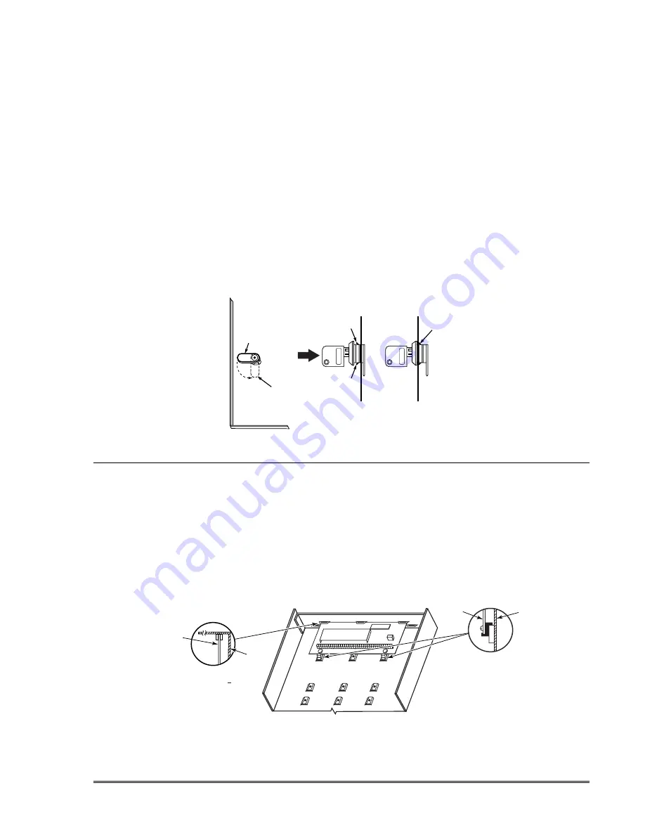
Cabinet and Lock 

1.  Mount the control cabinet to a sturdy wall in a clean, dry area, which is not readily accessible to 

the general public, using fasteners or anchors (not supplied) with the four cabinet mounting 
holes. 

2.  Remove cabinet door, then remove the lock knockout from the door. Insert the key into the lock.  

3.   Position the lock in the hole, making certain that the latch will make contact with the latch 

bracket when the door is closed. When correctly positioned, push the lock until it is held securely 
by its snap tabs. 


NOTES


 The cabinet can be closed and secured without a lock by using 2 screws in the cover's edge. 


CABINET DOOR

BOTTOM

LOCKED

UNLOCKED

cab_loc

k_snap-001-V0

ADEMCO

ADEMCO

PUSH

SNAP

TAB

SNAP

TAB

PUSH

ON LOCK

UNTIL IT

IS SEATED

SECURELY

STEP 2

STEP 1

CHECK

POSITION


Figure 1. Installing the Cabinet Lock


Mounting the PC Board Alone 

(no RF Receiver) 

1.  Hang two short mounting clips (provided) on the raised cabinet tabs (see Detail B in Fig. 2). 
2.  a.  Insert the top of the circuit board into the slots at the top of the cabinet. Make sure that the 

board rests on the correct row (see Detail A). 


b.  Swing the base of the board into the mounting clips and secure the board to the cabinet with 

the accompanying screws (see Detail B). 


NOTES


 Before installing the cabinet's contents, remove the metal cabinet knockouts required for wiring 

entry. Do not remove the knockouts after the circuit board has been installed. 


+

+

CIRCUIT

BOARD

DETAIL B

SIDE VIEW

OF MOUNTING

CLIPS

DETAIL A

SIDE VIEW

OF BOARD   

SUPPORTING

SLOTS

CIRCUIT

BOARD

MOUNTING-001-V0

CABINET

CABINET


Figure 2.  Mounting the PC Board 


2-1 

Summary of Contents for ADEMCO VISTA-10P

Page 1: ...ADEMCO VISTA 10P ADEMCO VISTA 10PSIA Security Systems Installation and Setup Guide K0735V3 10 04 Rev B ...

Page 2: ...the hallway outside may not wake up the sleeper if the door is closed DINING KITCHEN BEDROOM BEDROOM BEDROOM BEDROOM LIVING ROOM BEDROOM BDRM BDRM DINING LIVING ROOM TV ROOM KITCHEN BEDROOM BEDROOM TO BR LVNG RM BASEMENT KTCHN CLOSED DOOR GARAGE Smoke Detectors for Minimum Protection Smoke Detectors for Additional Protection Heat Activated Detectors floor_plan 001 V0 Install a smoke detector insid...

Page 3: ...talling a Keyswitch 2 8 Connecting Relay Modules 2 9 On Board Triggers 2 10 Phone Line Phone Module Connections 2 10 Long Range Radio Connections 2 11 AAV Connections 2 12 Programming Overview 3 1 About Programming 3 1 Keypads 3 1 Wireless Receiver Transmitters and Wireless Keys keyfobs 3 2 Pager Programming 3 2 Function Keys 3 2 Output Devices 3 2 Zone Type Definitions 3 3 Mechanics of Programmin...

Page 4: ...2 Menu Mode 5 11 Programming Zone Descriptors Menu mode 82 5 11 Adding Custom Words 5 12 Programming Installer and User Schedules 5 14 System Communication and Operation 6 1 System Communication Overview 6 1 Report Code Formats 6 1 Ademco Contact ID 6 3 User Security Codes 6 4 Keypad Functions 6 5 Various System Trouble Displays 6 6 Testing the System 7 1 About Test Procedures 7 1 System Test 7 1 ...

Page 5: ...n detects external sounder wiring short or open causes a trouble condition keypad display and sends a report to the central monitoring station if enabled Optional RF jam detection for wireless systems detects a condition that may impede proper RF reception i e jamming or other RF interference causes keypad display and sends a report to the central monitoring station if trouble reporting is enabled...

Page 6: ...n data fields 190 196 4204 Relay Modules must be set for specific address 12 see Connecting Relay Modules section Relays have two programming menu modes Use 79 Menu mode to map module addresses and device output numbers Use 80 Menu mode to define the output functions see Output Device Programming section This system supports programmable function keys Use 57 Menu mode to define the function keys s...

Page 7: ...001 V0 ADEMCO ADEMCO PUSH SNAP TAB SNAP TAB PUSH ON LOCK UNTIL IT IS SEATED SECURELY STEP 2 STEP 1 CHECK POSITION Figure 1 Installing the Cabinet Lock Mounting the PC Board Alone no RF Receiver 1 Hang two short mounting clips provided on the raised cabinet tabs see Detail B in Fig 2 2 a Insert the top of the circuit board into the slots at the top of the cabinet Make sure that the board rests on t...

Page 8: ...d terminals and tighten the screws NOTES Do not mount the cabinet on or near metal objects This will decrease RF range and or block RF transmissions from wireless transmitters Do not locate the cabinet in an area of high RF interference revealed by frequent or prolonged lighting of the LED in the receiver after it is operational random flicker is OK ANTENNA MOUNT 2 PLACES ANTENNA 2 SCREW 2 BLACK M...

Page 9: ...CTLY TO SCREW TERMINALS AS SHOWN TO KEYPAD RED WIRE TO KEYPAD BLK WIRE TO KEYPAD YEL WIRE TO KEYPAD GRN WIRE TO KEYPAD BLK WIRE TO KEYPAD RED WIRE TO KEYPAD GRN WIRE TO KEYPAD YEL WIRE supp_pwr_supply V0 Figure 4 Using a Supplementary Power Supply UL Use a UL Listed battery backed supply for UL installations The battery supplies power to these keypads in case of AC power loss The battery backed po...

Page 10: ...utput and the auxiliary power output combined cannot exceed 600 mA In addition the sounding device must be a UL Listed audible signal appliance rated to operate in a 10 2 13 8 VDC voltage range and must be mounted indoors Wiring the AC Transformer Connect the 1321 Transformer to terminals 1 and 2 on the control board See Wire Run Chart for wire size to use Use 1321CN in Canada NOTES Wire Run Chart...

Page 11: ...ed to the pipe to which the ground lead is electrically connected and secured AC Power Outlet Ground Available from 3 prong 120VAC power outlets only To test the integrity of the ground terminal use a 3 wire circuit tester with neon lamp indicators such as the UL Listed Ideal Model 61 035 or equivalent available at most electrical supply stores This product has been designed and laboratory tested ...

Page 12: ...2000 OHMS EOLR HEAT DETECTOR RED EOL POWER SUPERVISION RELAY MODULE A77 716B USE N O CONTACT WHICH CLOSES WHEN POWER IS APPLIED VIOLET AUX PWR OUTPUT TERMINALS 5 4 _ _ _ BLK _ 4_wiresmk 007 V0 TO ZONE TERM TO ZONE TERM RELAY CONTACT OPENS MOMENTARILY UPON FIRE ALARM RESET PROGRAM RELAY AS ZONE TYPE 54 FIRE ZONE RESET 4 WIRE SMOKE OR COMBUSTION DETECTOR N C N O 2000 OHMS EOLR HEAT DETECTOR RED VIOL...

Page 13: ...equent or prolonged lighting of the LED in the receiver random flicker is OK Do not locate RF receiver closer than 10 feet from any keypads to avoid interference from the microprocessors in those units MOUNTING HOLES INTERFERENCE INDICATOR LED CIRCUIT BOARD DIP SWITCH ANTENNAS INSERT IN RIGHT HAND TERMINALS YELLOW RED BLACK GREEN WIRING OPENING KNOCKOUT AREA FOR SURFACE WIRING TO CONTROL S REMOTE ...

Page 14: ...laceable batteries and no battery installation is required At the end of their life the complete unit must be replaced and a new serial number enrolled by the control Button type transmitters such as 5801 5802 and 5802CP should be periodically tested for battery life The 5802MN and 5804 Button Transmitters have replaceable batteries Do not install batteries in wireless transmitters until you are r...

Page 15: ... the connector harness supplied with the module Use standard 4 conductor twisted cable for long wiring runs 3 Set the module s device address to address 12 4 Connect the desired field wiring to the unit s relay contact terminals NOTES Use 4204 module Supervision 4204 module is supervised against removal The module s device address is displayed as follows if a module is disconnected from the contro...

Page 16: ...support 12V relay module that draws less than 20mA e g Altronix AX RBS Phone Line Phone Module Connections 1 Connect incoming phone line and handset wiring to the main terminal block via an RJ31X jack as shown in the Summary of Connections diagram at the back of this manual Wire colors represent the colors of the cable to the RJ31X jack If using a phone module continue with the following steps 2 M...

Page 17: ... PIPE ETC UNUSED KEYED HEADER 4285 4286 VIP MODULE 1 2 3 4 5 6 7 YELLOW TO DATA OUT term 7 NO CONNECTION RED TO AUX term 5 BLACK TO AUX GROUND term 4 GREEN TO DATA IN term 6 CONNECTOR WITH FLYING LEADS TO CONTROL PANEL TERMINALS USED FOR KEYPAD CONNECTIONS PREMISES ANSWERING MACHINE AND PHONES HANDSET INCOMING TELCO LINE TIP RING PLUG DIRECT CONNECT CORD TIP RING GROUND TIP RING GREEN TIP RED RING...

Page 18: ... T TRIGGER CONNECTOR OUTPUT 18 EOL RING TIP OPTIONAL MONITORING ZONE CONNECTION USE ZONE TYPE 81 FALLING VOICE TRIG GND 12VDC IN SWITCH BANK 2 SWITCH BANK 1 SWITCH BANK 2 SWITCH BANK 1 AUXILIARY AUDIO LEVEL ADJUSTMENT TRIM POT aav_uvcm 003 V0 CONTROL INCOMING PHONE LINE TO PREMISES HANDSET 5 1 ON 2 ON 3 OFF 4 ON 5 ON 6 ON 7 ON 8 ON 1 OFF 2 OFF 3 OFF 4 OFF 5 OFF 6 OFF 7 OFF 8 ON 23 24 25 12VDC GND ...

Page 19: ... those more experienced in programming controls of this type 79 Output Device Mapping Assign device address of the 4204 Relay module and map the specific relays 80 Output Definitions Define up to 12 output definitions which can control the output relays mapped using 79 Output Device Mapping mode 81 Zone List Programming Create Zone Lists for relay zones chime night stay cross zones and pager zones...

Page 20: ... for the Latchkey report to be sent 5 If using a function key to manually send a message to a pager see Function Keys paragraph on the next page 6 If reporting zone alarms and troubles to a pager use 81 Zone List menu mode to assign the zones associated with each pager zone lists 9 Function Keys To assign functions to the function keys use 57 Function Key menu mode To assign emergency key function...

Page 21: ...ssed when system armed in Night Stay mode Type 05 Trouble by Day Alarm by Night Assign to a zone that contains a foil protected door or window such as in a store or to a zone covering a sensitive area such as a stock room drug supply room etc Can also be used on a sensor or contact in an area where immediate notification of an entry is desired Provides an instant alarm if faulted when armed in the...

Page 22: ...nits send the user number to the central station when arming or disarming User number for button must be assigned Type 22 Disarm BR only Disarms the system when the zone is activated User number for button must be assigned Type 23 No Alarm Response Can be used on a zone when an output relay action is desired but with no accompanying alarm e g lobby door access Type 24 Silent Burglary Usually assig...

Page 23: ...79 80 81 82 Entering Menu Mode Press Menu Mode No for example 56 while in Program Mode The Alpha display keypad displays the first of a series of prompts After making the appropriate entry press the key to accept the entry and continue to the next prompt Loading Factory Defaults Initializing for Download To Load Default Entries Press 97 while in Program Mode This resets all data fields to the defa...

Page 24: ...pad 3 keypad 4 keypad 5 keypad 6 keypad 7 keypad 8 16 17 18 19 20 21 22 23 n a n a n a n a n a n a n a n a data field programming as listed below always enabled all sounds enabled data field 190 data field 191 data field 192 data field 193 data field 194 data field 195 data field 196 5800TM Module 28 n a automatic Addressable devices are identified by 1 plus the device address when reporting Enter...

Page 25: ... UL installations must be 1 if wireless devices are used 23 Quick Forced Bypass Select whether or not the Quick Bypass command code 6 is active Zones bypassed by this function will be displayed after the bypass is initiated UL installations must be 0 no forced bypass 24 RF House ID Code Enter the RF House ID which identifies receivers and wireless keypads If a 5827 or 5827BD Wireless Keypad or 580...

Page 26: ...result in a 45 sec delay 35 Entry Delay 1 Enter the desired time within which the system must be disarmed after opening an entry door If this time expires without disarming an alarm occurs UL installations For UL Residential Burglary Alarm installations must be set for a maximum of 30 seconds entry delay plus dial delay should not exceed 1 min For UL Commercial Burglar Alarm total entry delay may ...

Page 27: ... phone lines from the list on the Programming Guide 49 Split Dual Reporting Select the desired type of reports to be sent to the primary secondary numbers Make selection from the table in the Programming Guide If 0 selected all reports go only to the primary number unless unsuccessful then control will attempt to dial secondary number 50 Burglary Dialer Delay Enter the desired delay time none 15 3...

Page 28: ...scribed above 0 in the first box disables a report 0 in the second box eliminates the expanded message for that report ADEMCO Contact ID Reporting Enter a digit in the first box to enable the zone to report Use a different digit for each zone until you have used up available digits If the number of zones exceeds the number of available digits begin with digit 1 again This is an enabling code only ...

Page 29: ...t upon disarming of the system after an alarm was reported VISTA 10PSIA Default code enabled 69 Recent Closing Report VISTA 10PSIA only Always enabled Field does not apply to other controls Similar to the Exit Error condition described in field 59 but occurs if any burglary zone is faulted within two minutes after the initial exit delay expires Disarming the system within the two minutes stops the...

Page 30: ... which two cross zones must be tripped in an armed system to send an alarm message to the Central Station If only one cross zone is tripped during this time a trouble message CID code 380 for that zone is sent to the Central Station Assign cross zone pairs in zone list 4 This option not for use in UL installations 86 Cancel Verify Keypad Display Select whether ALARM CANCELED is displayed on the LC...

Page 31: ... secondary number by the communicator after the alarm report will prevent the AAV from taking control of the telephone line and the AAV Listen in session cannot take place UL UL installations using the AAV feature must use the ADEMCO UVCM module part of the ADEMCO UVS system Exit Delay Restart Reset must be disabled SIA Guidelines Exit delay should be enabled 93 No of Reports In Armed Period per Z...

Page 32: ... be entered If fewer than 16 characters exit by pressing and next field number To clear entries from this field press 161 For example these optional 16 characters may be composed of the following paging company PIN number subscriber account number enter 11 to send enter 12 to send pause enter 13 to allow a 2 second pause some paging systems require pause Any special character s the end user may de...

Page 33: ...protected if the zone is later restored e g an open window can be ignored when arming but if the window is later closed it will be protected opening the window again causes an alarm Bypass Disarmed entry 4 Zones set for this option can be bypassed only while the system is disarmed Bypass Armed entry 4 Zones set for this option can be bypassed when the system is armed or disarmed Dial Delay entry 6...

Page 34: ...rms trbles faults when disarmed 3 never show any alarms trbles faults 0 no 4 power reset after fault with code OFF 12 verification see zone type 16 0 no 1 delay 1 2 delay 2 0 no 4 use exit delay 0 no 8 yes see note 2 Entry 7 fault display power reset verification Entry 8 entry delay 1 entry delay 2 exit delay interior zone type ENTRY 9 ENTRY 10 Alarm Sounds Use Bell Timeout Respond as Fire Zone Tr...

Page 35: ... Time Display Interval Select whether or not keypads display the exit time remaining after arming the system with display updates at the interval selected i e if the exit delay is 30 seconds and 2 is selected in this field the keypad display refreshes every 2 seconds displaying 30 28 26 24 etc An interval greater than 1 may be necessary for some older keypads to allow users time to enter key press...

Page 36: ...Installation Instructions 4 12 ...

Page 37: ...at the XMIT TO CONFIRM prompt later in this procedure We recommend that you confirm the programming of every transmitter Enter Zn Num 00 Quit 10 Enter the zone number that you wish to program e g zone 10 as shown in the display wired zones 01 06 wireless zones 09 24 button zones 49 56 Enter a report code for zone 91 to enable addressable device reporting Enter a report code for zone 92 to enable d...

Page 38: ...ignals transmitter may be carried off premises 5 BR unsupervised button type RF transmitter sends fault and low battery signals when activated does not send restore or check in signals transmitter may be carried off premises to continue 10 INPUT S N L A022 4064 1 For wireless transmitters enroll the serial number and loop number 1 a Transmit two open close sequences If using a button type transmit...

Page 39: ...ng wireless transmitting devices as it will only check for transmission of one zone on a particular transmitter NOT the zones assigned to each additional loop NOTE Following the successful enrollment of each wireless device note the device serial number in the appropriate column on the ENROLLED TRANSMITTERS worksheet in the Programming Form then enter the other information zone number zone type lo...

Page 40: ...nd re enter or edit the serial number If the serial number transmitted matches the serial number entered the keypad will beep 3 times and a summary display will appear showing the programmed information for that zone Press to begin programming the next zone See first Summary Screen prompt paragraph Wireless Key Programming Templates This procedure programs the wireless keys but a key is not active...

Page 41: ...e Zone Number prompt IMPORTANT When confirmed the key is not active for arming disarming until it is assigned to a user number using the assigning attributes command attribute 4 See System Operation section to skip confirm Wireless Key Predefined Default Templates YOU MUST PROGRAM THIS BUTTON LOOP 4 LOOP 3 ENROLL AS BR LOOP 1 LOOP 2 ON OFF 5804 001 V1 5804 Wireless Key Transmitter Note These trans...

Page 42: ...menu to assign the Relay Module device address and specific relay numbers The system is based on predefined module addresses The address for the 4204 is 12 Refer to the Module Address prompt on the next page and set the module s address via module DIP switches accordingly Start Output Device Mapping by pressing 79 while in Data Programming Mode The following prompts are displayed 79 Menu Mode PROM...

Page 43: ... to define another output function number with the same attributes but assign the appropriate output number i e output devices can be assigned more than one function number but each function number can only be assigned a single output number For example if you want to pulse a strobe light upon fire alarms on zone 4 using a relay mapped to output number 2 as programmed in 79 Menu Mode program the f...

Page 44: ...Fire Alarm 58 Duress 31 End of Exit Time 40 Bypassing 60 AAV 32 Start of Entry Time 41 AC Power Failure 66 Function Key 33 Any Burglary Alarm 42 System Battery Low 67 Bell Fail 43 Comm Failure 68 Telco line cut 78 Keyswitch Red LED 79 Keyswitch Green LED Or at Disarming whichever occurs earlier Use 57 Menu Mode to assign the function key function 07 Note In normal operation mode Code 7 NN Key Entr...

Page 45: ...report code for zone 92 to enable duress reporting 95 96 99 emergency zones 00 to continue IMPORTANT Do not include fire zones in zone lists that are used to STOP device actions 01 Del Zn List 0 No 1 Yes 0 To delete the zone list enter 1 All zones in the zone list will be deleted automatically and the system returns to the Zone List No prompt To save the zone list enter 0 to continue 01 Delete Zon...

Page 46: ... 9 8 7 0 READY INSTANT MAX OFF CODE AWAY TEST CHECK STAY BYPASS A B C D keypad_keys 00 001 V0 Key A Func Zone 95 00 Enter the desired function for this key 00 For the Function key selected the function will be as follows system default If A selected Zone 95 emergency key same as 1 pair If B selected Zone 99 emergency key same as pair If C selected Zone 96 emergency key same as 3 pair If D selected...

Page 47: ...es the entered descriptor and moves to the next descriptor Start Zone Descriptor Programming mode by pressing 82 while in Data Programming mode PROMPT VALID ENTRIES and EXPLANATION Program Alpha 0 No 1 Yes 0 Press 1 to program descriptors 0 exit this mode Custom W ords 0 No 1 Yes 00 To program standard alpha descriptors from the fixed vocabulary press 0 The system will then automatically display t...

Page 48: ...ustom zone descriptors a custom message replaces DISARMED READY TO ARM and reminder words for Scheduling mode event 10 NOTE Do not assign reminder words if using fixed word keypads 1 yes program custom words or reminder words 0 no go to zone descriptors see above If 1 selected enter the 2 digit custom word number 01 10 to be programmed corresponding to index numbers 245 254 respectively for exampl...

Page 49: ...ATION 160 RF 161 RIGHT 162 ROOM 163 ROOF S 164 SAFE 165 SCREEN 166 SENSOR 167 SERVICE 168 SHED 169 SHOCK 170 SHOP 171 SHORT 173 SIDE 174 SKYLIGHT 175 SLIDING 176 SMOKE 178 SONS 179 SOUTH 180 SPRINKLER 182 STATION 184 STORE 185 STORAGE 186 STORY 190 SUPERVISED 191 SUPERVISION 192 SWIMMING 193 SWITCH T 194 TAMPER 196 TELCO 197 TELEPHONE 199 TEMPERATURE 200 THERMOSTAT 201 TOOL 202 TRANSMITTER U 205 U...

Page 50: ...vent 01 Relay On Off 02 User Access 03 Latch Key Report to Pager sent to all pagers and is active only when the system is armed message sent is 777 7777 user must be enabled for paging see User Attributes in System Operation section 04 Forced Stay Arming forced bypass is automatically enabled regardless of setting in field 23 05 Forced Away Arming forced bypass is automatically enabled regardless ...

Page 51: ...option for this schedule e g To make a schedule that happens everyday you would select all days with a repeat count of 1 To make a schedule that runs for one week then stops select everyday with a repeat count of 0 0 do not repeat 1 repeat schedule weekly 2 repeat schedule biweekly every other week 3 repeat every 3rd week 4 repeat every 4th week to continue RANDOMIZE 0 NO 1 YES X Select whether yo...

Page 52: ...Installation Instructions 5 16 ...

Page 53: ...r if programmed to get a valid message through If the panel is not successful after its numerous attempts the keypad displays COMM FAILURE on alpha keypads or FC on fixed word keypads Report Code Formats The following chart indicates the types of handshake kissoff frequencies that the panel supports and the different formats that can be sent with each FORMAT HANDSHAKE TRANSMITS DATA KISSOFF TRANSM...

Page 54: ... SSSSRA Ac RARARA RA Ac LoBat Res SSS S RL SSS S RL SSSS RLLB RLRLRL RL LB Trouble Res SSS S RT SSS S RT SSSS RTt RTRTRT RT t Bypass Res SSS S RB SSS S RB SSSS RBb RBRBRB RB b Where SSS or SSSS Subscriber ID C Close Code 1st Digit A Alarm Code 1st digit U User Number in hex Z Typically Zone Number 2nd digit Gg Test Code 1st 2nd digits Tt Trouble Code 1st 2nd digits R Restore Code Alarm Bb Bypass C...

Page 55: ...ule 145 ECP Module cover tamper 146 Silent Burglary 150 Alarm 24 Hour Auxiliary Monitor zone 162 Carbon Monoxide 301 AC Power 302 Low System Battery Battery Test Fail 305 System Reset Log only 309 Battery Test Failure 321 Bell Siren Trouble 333 Trouble Expansion Mod Supervision 341 Trouble ECP Cover Tamper 344 RF Receiver Jam 351 Telco Line Fault 353 Long Range Radio Trouble 373 Fire Loop Trouble ...

Page 56: ...for procedures on adding deleting security codes and changing attributes The following is a brief description of how to add user codes Changing the System Master code Using Installer code Installer code 8 02 new code Using current System Master code System Master code 8 02 new code new code again Adding a User Code Master code 8 2 digit user no user s code Deleting a User Code Master code 8 2 digi...

Page 57: ... system will automatically arm in STAY mode if armed from a wired keypad non RF device If the door is opened and closed within the exit delay period the system arms in AWAY mode Arming Stay Enter code STAY 3 or simply press appropriate key on the keypads see Single Button Arming above See Arming Away above for Auto Stay arming feature Arming Night Stay Enter code STAY 3 STAY 3 or simply press appr...

Page 58: ...e system the Check condition may also be caused by some change in the environment that prevents the receiver from receiving signals from a particular sensor SYSTEM LO BAT BAT with no zone number indicates that the system s main standby battery is weak LO BAT BAT with a zone number and a once per minute beeping at the keypad indicates that a low battery condition exists in the wireless sensor displ...

Page 59: ...ckup battery is discharged or missing the sounder may not turn on and a LOW BATTERY report will be transmitted with a TEST report The keypad will beep about every 40 seconds as a reminder that the system is in the Test mode NOTE Wireless motion detectors Passive Infrared units will send signals out only if they have been inactive for 3 minutes conserves battery life 3 Test all sensors using the pr...

Page 60: ... to manually test communication to the central station 1 Enter Installer Code 5 TEST then press 1 at the prompt to start the Dialer Test 1 DIAL 0 WALK no special display on Fixed Word Display Keypads The following will be displayed accompanied by 2 beeps if test is successful PHONE OKAY Cd displayed on Fixed Word Display Keypads A Contact ID report will also be sent code 601 If the dialer test is ...

Page 61: ...Radionics SESCOA 20 pulses sec 1800Hz Data Tone 2300Hz ACK KISSOFF Can report 0 9 B F Ademco Contact ID 10 characters sec DTMF TouchTone Data Tones 1400 2300Hz ACK 1400Hz KISSOFF LINE SEIZE Double Pole RINGER EQUIVALENCE 0 1B FCC REGISTRATION No 5GBUSA 44003 AL E COMPATIBLE DEVICES Keypads 6150 6160 6150V 6160V Wireless Receivers 5881L 5882L accepts up to 8 transmitters 5881M 5882M accepts up to 1...

Page 62: ... 5802MN2 5804 5804BD 5814 5816TEMP 5819 5819WHS BRS and 5850 Compatible 5800 Series Transmitters Table Model Product Input Type Description 5801 Wireless Panic Transmitter UR or RF Four pushbuttons each with a unique input loop code Programmable responses e g Panic Arm Disarm etc 5802 Pendant Personal Emergency Transmitter BR Only Has single pushbutton Usually programmed for response type of 24 Hr...

Page 63: ...3 unique input loop codes Loop 1 Built in shock sensor loop wired to TB1 normally closed Loop 2 For a closed circuit contact loop using the built in reed switch in conjunction with a magnet Loop 3 Externally wired closed circuit loop connected to TB2 5827 Wireless Keypad Uses House ID only Can be used to turn the burglary protection on and off Features the same built in panic functions as wired ke...

Page 64: ...Installation Instructions 8 4 ...

Page 65: ... to make such connections themselves but should contact appropriate electric inspection authority or electrician as appropriate Ringer Equivalence Number Notice The Ringer Equivalence Number REN assigned to each terminal device provides an indication of the maximum number of terminals allowed to be connected to a telephone interface The termination on an interface may consist of any combination of...

Page 66: ...wing UL requirements per UL681 are provided The maximum time that a control unit shall be programmed to delay the transmission of a signal to a remote monitoring location or to delay the energizing of a local alarm sounding device to permit the alarm system user to enter and disarm the system or to arm the system and exit shall not exceed a 60 seconds for a system with standard line security or en...

Page 67: ...aping gas improper storage of flammable materials overloaded electrical circuits children playing with matches or arson Depending on the nature of the fire and or location of the smoke detectors the detector even if it operates as anticipated may not provide sufficient warning to allow all occupants to escape in time to prevent injury or death Passive Infrared Motion Detectors can only detect intr...

Page 68: ...actors such as humidity high or low temperatures as well as large swings in temperature may all reduce the actual battery life in a given installation This wireless system however can identify a true low battery situation thus allowing time to arrange a change of battery to maintain protection for that given point within the system Installing an alarm system may make the owner eligible for a lower...

Page 69: ...1 4 7 Exit Delay 4 2 4 7 4 9 6 5 6 6 Exit Error Alarm 6 6 Exit Error Report Code 4 4 Expert Programming Mode 5 3 5 5 F Factory Defaults 3 5 Fast Busy Signal 2 11 Fault Delay Time 4 6 Function Key Programming 1 2 3 1 5 10 Function Keys 3 2 5 10 Fuse 8 1 G Go No Go Test Mode 7 2 H Handshake 6 1 hardwired zones 1 1 6 6 HAYES Modem 1 1 House ID 2 8 4 1 8 2 8 3 I IBM Personal Computer 3 1 Ideal Model 6...

Page 70: ...2 8 Transmitter Input Types 5 2 Trouble by Day 3 3 Trouble Displays 6 4 6 6 V Vocabulary List 5 11 W Wireless Key Templates 5 4 Wiring Length Gauge Chart 2 3 Wiring Run Chart 2 3 Word String 5 12 Worksheet 2 5 Z Zone Lists 3 1 5 9 Zone Programming Procedure 5 1 Zone Types 3 3 5 1 5 4 5 8 Installation Instructions 10 4 ...

Page 71: ...E 3 ZONE 4 HI LO HI LO ZONE 5 ZONE 6 HI LO HI LO MAXIMUM LOOP RESISTANCE EACH ZONE 300 OHMS PLUS EOLR RESPONSE ZONES 1 6 10 350 OR 700 MSEC PROGRAMMABLE 5 PIN CONNECTOR FOR ON BOARD TRIGGERS SEE INSTRUCTIONS USE KEYPAD CABLE TIP BROWN THIS DEVICE COMPLIES WITH PART 15 OF FCC RULES OPERATION IS SUBJECT TO THE FOLLOWING TWO CONDITIONS 1 THIS DEVICE MAY NOT CAUSE HARMFUL INTERFERENCE AND 2 THIS DEVIC...

Page 72: ...TION ON THE FACE HEREOF IN NO CASE SHALL SELLER BE LIABLE TO ANYONE FOR ANY CONSEQUENTIAL OR INCIDENTAL DAMAGES FOR BREACH OF THIS OR ANY OTHER WARRANTY EXPRESS OR IMPLIED OR UPON ANY OTHER BASIS OF LIABILITY WHATSOEVER EVEN IF THE LOSS OR DAMAGE IS CAUSED BY THE SELLER S OWN NEGLIGENCE OR FAULT Seller does not represent that the product s it sells may not be compromised or circumvented that the p...

Reviews: