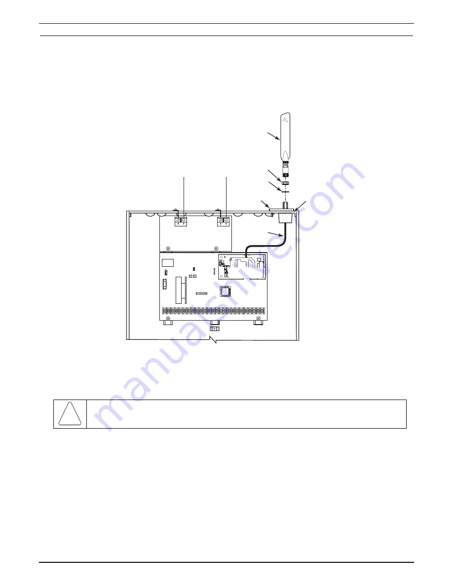
2. Install the Antenna Adapter Plate.
a. Punch out the large wiring hole knockout and the adjacent smaller knockout from the cabinet’s upper-right
topside.
b. Position the antenna adapter plate over the large knockout, aligning the plate’s pin with the smaller
knockout and push until the adapter snaps into place.
c. Remove the nut and washer from the antenna adapter cable, then secure the cable’s SMA connector to the
adapter plate with the washer and nut as shown.
VISTA-21iP CONTROL BOARD
ANTENNA
ADAPTER
CABLE
ANTENNA
ADAPTER
PLATE
V21iP-016-V1
ANTENNA
OPTIONAL
5800 SERIES
RECEIVER
LARGE
WIRING
HOLE
KNOCKOUT
WASHER
NUT
VISTA-GSM4G
MODULE
YEL
YEL
GRN
GRN
GRN
RED
3. Install the Antenna.
The antenna mounts directly onto the antenna adapter cable at the antenna adapter plate.
Carefully align the antenna’s connector over the SMA connector protruding from the adapter plate, then screw it
down (clockwise) until it is finger tight. Do not over tighten.
!
RF EXPOSURE WARNING
The VISTA-GSM4G module must be installed to provide a separation distance of at least 7.8 in. (20 cm) from all
persons and must not be co-located or operating in conjunction with any other antenna or transmitter except in
accordance with FCC multi-transmitter product procedures.
Internal/External IP/GSM Power Jumper Note:
After installation of the module, make sure the control’s PC
Board Internal/External IP/GSM Power Jumper is in the ON position (factory default position). The jumper is
located below the RJ45 connector.
Programming Overview
2-17
Summary of Contents for Ademco VISTA-21iPSIA
Page 26: ...Installation and Setup Guide 2 20 ...
Page 78: ...Installation and Setup Guide 6 8 ...
Page 84: ...Installation and Setup Guide 8 4 ...
Page 88: ...Installation and Setup Guide 9 4 ...
Page 89: ...Notes 9 5 ...


