Installation Instructions
4-10
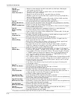
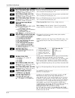
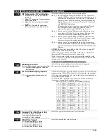
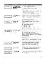
*163
Pager 2 Phone No.
Enter up to 20 digits
If you enter fewer than 20 digits, exit by pressing [
∗
] and next field
number. To clear entries from this field, press
∗
163
∗
.
*164
Pager 2 Characters
Enter up to 16 characters
See field
∗
161 for explanation. If fewer than 16 characters, exit by
pressing [
∗
] and next field number. To clear entries, press
∗
164
∗
.
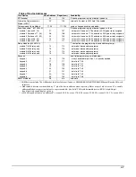
*165
Pager 2 Report Options
see pager 1 reports, field *162 for entries,
except use zone list 10.
Enter the types of reports to be sent to pager 2 for each partition.
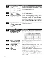
*166
Pager Delay Option for Alarms
0 = none
2 = 2 minutes
1 = 1 minute
3 = 3 minutes
This field determines the delay of alarm reports to the pager. This
gives the Central Station enough time to verify the alarm report that
it received, before the dialer attempts to dial the pager.
NOTE:
The delay does not reset for new alarms occurring while an
existing pager delay is in progress.
This delay is for ALL pagers in the system.
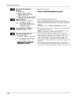
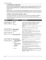
Miscellaneous System Fields
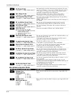
*173
RF REPORTING OPTIONS
0 = none
1 = RF Tamper reports during disarm
2 = RF keyfobs send low battery
3 = RF Tamper reports during disarm and
RF keyfobs send low battery
Select desired option.
*175
Tamper Options
Entry 1: 0 = standard tamper detection
1 = detect tamper from bypassed
zones
2 = detect tamper when in Test
mode
3 = detect tamper both when in Test
mode and from bypassed zones
Entry 2: 0 = all users can clear a tamper**
1 = only the installer can clear a
tamper
Select desired options.
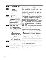
Standard Tamper Detection (entry 1 option 0): The system normally
detects tamper faults from devices equipped with tamper switches
(for cover removal and/or wall removal) while the system is armed or
disarmed. Tamper faults are ignored when a zone is bypassed or
when the system is in Test mode unless entry 1 options 1, 2, or 3 are
selected. Tamper display is as follows:
Disarmed:
TAMPER 1xx (or zz)
where 1xx = ECP device address
zz = zone number of faulted device.
Armed:
TMPR_ARMD
** Must be “0” if field *25 entry 2 is set for 1 or 2, otherwise, only the
installer will be able to disarm the system and clear tamper displays.
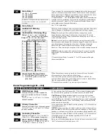
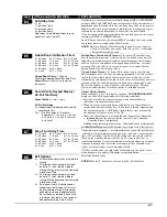
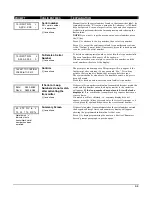
*176
Bell (Siren) Options
Entry 1: 0 = external bell (siren)
1 = self-activated external bell
Entry 2: 0 = disable siren delay
1 = external siren delay and dialer
delay during entry delay period
when armed AWAY
2 = enable stay siren delay
Select desired options.
Entry 2:
Option 1 – When entry delay is active (ex. reentering
premises while armed AWAY) and an instant zone is faulted, the
external siren is delayed 30 seconds and the dialer report is delayed
30 seconds, unless field *50 is set for a greater delay (the 30-second
dialer delay supersedes values less than 30 seconds set in field *50).
Option 2 – When armed in the Stay mode and an alarm event occurs,
the siren output will be delayed by the amount of time that the entry
delay 1 is set for..
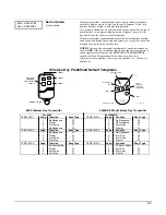
*177
Device Duration 1, 2
Duration 1 – Device Action 5 Timer
0 = 15 secs
6 = 2-1/2 min #+12 = 8 min
1 = 30 secs
7 = 3 min
#+13 = 10 min
2 = 45 secs
8 = 4 min
#+14 = 12 min
3 = 60 secs
9 = 5 min
#+15 = 15 min
4 = 90 secs
#+10 = 6 min
5 = 2 min
#+11 = 7 min
Duration 2 – Device Action 6 Timer
1 – 7 = 1 to 7 days
These entries set the duration for output action options 5 (duration 1)
and 6 (duration 2) programmed in
∗
80 Output Function
Programming.
Duration 2 can be used as a strobe timer.
Summary of Contents for ADEMCO VISTA-48D
Page 2: ...ii ...
Page 28: ...Installation Instructions 3 8 ...
Page 42: ...Installation Instructions 4 14 ...

