background image

L7224U OIL ELECTRONIC AQUASTAT

®

 CONTROLLER

3

69-1720—03

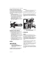
Fig. 2. Removing horizontal or vertical mounting 

knockout.

8.

Loosen but do not remove the well clamp screw.

9.

Fit the case into the well so the clamp on the case 

slides over the flange on the well.

10.

Securely tighten the clamp screw.

11.

Insert the sensor element into the well until it 

bottoms. (If necessary, slightly bend the wire inside 

the case to hold the sensor against the bottom of 

the well.)

12.

Turn power ON.

13.

Set High Limit, Low Limit and Differentials to the 

settings recommended by the boiler OEM. (See 

OPERATION section, also refer to INSTALLATION 

steps 6 and 7.)

IMPORTANT

Best thermal response is obtained with a well 
that snugly fits the sensor. Insert the sensor until 
it rests against the bottom of the well. Use a well 
of correct length and bend the wiring, if neces-
sary, to hold the bulb against the bottom of the 
well.

If the well is not a snug fit on the sensor, use the 
heat-conductive compound (furnished with 
TRADELINE

®

 models) as follows: Fold the 

plastic bag of compound lengthwise and twist it 
gently. Then snip off end of bag and work the 
open end of the bag all the way into the well. 
Slowly pull out the bag while squeezing it firmly 
to distribute compound evenly in the well. Bend 
the wiring, if necessary, to hold the sensor 
against the bottom of the well and to hold outer 
end of the sensor in firm contact with the side of 
the well. See Fig. 3.
 Wipe excess compound 
from the outer end of the well.

Fig. 3. Position of sensor in immersion well.

Flush-Mounted Aquastat Replacement

Turn off all power and remove the old controller. Refer to 
the cover insert of the old controller to identify and tag 
each external lead as it is disconnected. If the old well is 
unsuitable for the new installation, remove it and replace it 
with a suitable new well. If the old well is suitable, use it. 
See Fig. 1 and 4 for mounting tab location.

Fig. 4. Location of L7224U flush-mounting tabs and 

LEDs.

SCREWDRIVER

M22118

KNOCKOUT FOR

HORIZONTAL

MOUNT

KNOCKOUT FOR

VERTICAL MOUNT

SENSOR WIRES

IMMERSION WELL 

CLAMP SCREW

IMMERSION

WELL CLAMP

M16120

HEAT-CONDUCTIVE COMPOUND

(OPTIONAL)

CONTROLLER CASE

BOILER

IMMERSION 

WELL

SENSOR

C1

B1

ZC

L2

LINE

C2

ZR

TX

L1

B2

T
T 3

2
1

THERMOSTAT

TERMINALS

ENVIRACOM

TM

TERMINALS

DISPLAY

SENSOR

CONNECTOR

SENSOR HOLES

FUSE

RELAYS

RELAY

FLUSH MOUNTING TAB (2)

M22119A

TRANSFORMER

CAPACITOR

LED's

TT

B1 ZC C1

Summary of Contents for Aquastat L7224U

Page 1: ...Relay 7 4 A at 120 Vac FLA 44 4 A inrush LRA Zone Controller ZC 7 4 A at 120 Vac FLA 44 4 A inrush LRA NOTE All loads combined cannot exceed 2000 VA Environmental Ratings Temperature 30 F to 150 F 34 C to 66 C Humidity 0 to 95 relative humidity noncondensing Approvals Underwriters Laboratories Inc Component Recognized Canadian Underwriters Laboratories Inc Component Recognized Accessories Ordered ...

Page 2: ... position or flush mounted remote from the well IMPORTANT Immersion well must fit sensing element and sensor must rest against bottom of well New Installation Order well assemblies separately refer to Table 1 and form no 68 0040 Immersion Wells and Compression Fittings for Temperature Controllers Boilers usually have tappings that allow the well to be mounted horizontally so boiler water of averag...

Page 3: ...f bag and work the open end of the bag all the way into the well Slowly pull out the bag while squeezing it firmly to distribute compound evenly in the well Bend the wiring if necessary to hold the sensor against the bottom of the well and to hold outer end of the sensor in firm contact with the side of the well See Fig 3 Wipe excess compound from the outer end of the well Fig 3 Position of sensor...

Page 4: ... connections to prevent electrical shock or equipment damage All wiring must comply with local electrical codes and ordinances Do not exceed the specifications in the Application section when wiring this controller IMPORTANT The terminals on these Aquastat Controllers are approved for use with copper wire only Follow the appropriate wiring diagrams shown on the inside of the front cover of the L72...

Page 5: ...econds Press the I button until the feature requiring adjustment is displayed HL_ High Limit Hdf High Limit Differential LL_ Low Limit Ldf Low Limit Differential duu ZR input configured as external Domestic Hot Water DHW request ON OFF ASC Anti Short Cycle Timeout seconds OFF is disabled otL Outdoor Temperature Low minimum parameter for the outdoor reset curve F or C otH Outdoor Temperature High m...

Page 6: ...t setpoint with the adjustable Differential at the minimum setting of 10 F 6 C the burner circuit makes and the circulator circuit breaks Refer to Fig 7 Fig 8 Setpoints and differentials Boiler Temperature Description Display Shows High Limit Differential Low Limit L7224 only Low Limit Differential L7224 only Local Thermostat Status EnviraCOM Thermostat Status Boost Step Warm Weather Shutdown Temp...

Page 7: ...mand ZR Domestic Hot Water DHW Request The ZR terminal on the L7224U can be selected to service an indirect water heater heat request This parameter is set via the 3 digit display see Adjusting Settings section of this document A heat request via the ZC terminal will have priority over all other features such as the Anti Short Cycle feature or those enabled by the Outdoor Reset Module See form69 2...

Page 8: ...with outdoor reset parameters enabled as programmed Error cleared automatically Error condition 11 System continues to run with boiler temp set to High Limit Table 4 L7224 Controller Operating Sequence with multiple zones connected through the ZR terminal Action System Response Zone Request ZR terminal is connected to L1 Zone calls for heat Boiler temperature is checked Burner starts when water te...

Page 9: ...leared WARNING Electrical Shock Hazard Can cause severe injury or death All circuits must have a common disconnect to prevent the possibility of electrical shock Aquastat Error Code Cause Action EnviraCOM Alarm Err1 Aquastat sensor fault check water sensor 18 Err2 ECOM fault check EnviraCOM wiring 18 Err3 Excessive electrical noise or frequency out of range Hardware fault replace controller 18 58 ...

Page 10: ...y is ON TT LED is ON B1 LED is ON 120 Vac at B1 B2 If no replace controller If yes check burner and wiring Display is ON TT LED is ON Refer to Err on display Boiler is hot house is cold Display is ON TT LED is ON C1 LED is ON 120 Vac at C1 C2 120 Vac at C1 C2 check wiring to pump Wiring ok is pump running If not replace the pump If pump is running check for trapped air or closed zone valves Displa...

Page 11: ...ING SCREW PROVIDED 2 3 L1 HOT L2 1 2 1 4 5 6 ZONE 2 LOW VOLTAGE THERMOSTAT R845A RELAY ZONE 2 ZONE 2 CIRCULATOR TO ADDITIONAL R845A RELAYS FOR OTHER ZONES C1 B1 ZC L2 LINE C2 ZR L1 B2 T T 3 2 1 SENSOR LINE VOLTAGE CIRCULATOR LINE VOLTAGE OIL BURNER RELAY 2 LOW VOLTAGE THERMOSTAT L7248L ENVIRACOM TERMINALS OPTIONAL OUTDOOR RESET MODULE AND OUTDOOR SENSOR SHOWN 3 4 1 2 3 OT OT C7089U OUTDOOR SENSOR ...

Page 12: ... 2 2 2 1 1 1 SENSOR LINE VOLTAGE CIRCULATOR L7224 3 4 3 3 5 BURNER MOTOR IGNITOR VALVE BURNER MOTOR IGNITOR VALVE CAD CELL JUNCTION BOX TO REMOTE ALARM CIRCUIT ENVIRACOM TERMINAL TH9421C R7184 LIMIT L1 L2 2 CAD CELL T T3 2 1 L1 HOT L2 1 LEGEND SCREW TERMINAL 1 4 IN 6 MM QUICK CONNECT TERMINAL SOLDERLESS WIRE CONNECTION VALVE IS OPTIONAL ON SPECIFIED MODELS ENVIRACOM TERMINAL 3 IS ALSO THE FIRST TH...

Page 13: ... lubricant compounds Section 3 Hazard Identification Acute Health Effects Skin Excessive contact may cause skin irritation and dermatitis Eye Direct contact with eye will cause irritation Inhalation No adverse effects are expected Ingestion Ingestion of product may cause nausea vomiting and diarrhea Chronic Health Effects Existing skin rash or dermatitis may be aggravated by repeated contact OSHA ...

Page 14: ...gles or faceshield if potential for eye contact exists especially if material is heated Hand Clothing Protection Not normally required Protective gloves and clothing are recommended as material is difficult to remove from skin and clothing Other Protective Equipment None required Section 9 Physical and Chemical Properties Appearance Odor Aluminum color semi solid material pleasant odor Solubility ...

Page 15: ...L7224U OIL ELECTRONIC AQUASTAT CONTROLLER 15 69 1720 03 ...

Page 16: ...olutions Honeywell International Inc Honeywell Limited Honeywell Limitée 1985 Douglas Drive North 35 Dynamic Drive Golden Valley MN 55422 Toronto Ontario M1V 4Z9 customer honeywell com U S Registered Trademark 2009 Honeywell International Inc 69 1720 03 M S Rev 08 09 ...

Reviews: