L8100A,B,C Aquastat
®
CONTROLLERS
60-2336—3
3
Available Options:
External adjustment screw and visible control point scale.
Factory set stop at 140
°
F (60
°
C).
Approvals:
Underwriters Laboratories Inc. Component Recognized:
File No. MP466, Guide Number MBPR2.
American Gas Association Design Certified: Report
Number 23-11B.
Part Available:
110641 Jumper to convert four-terminal L8100 to three-
terminal L8100.
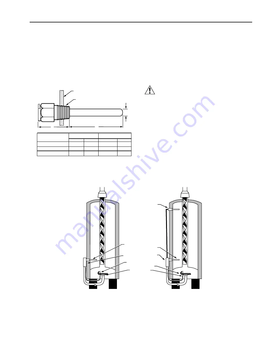
1/2 OR 3/4 — 14 NPT
C
B
A
M4746
CONTROLLER WELL
REMOTE WELL
A INSULATION DEPTH
B INSERTION DEPTH
C WELL DIAMETER
IN.
MM
2-1/4
5
7/16
57
127
11
1-1/2 OR 2-1/2
3
7/16
38 OR 64
76
11
TANK WALL
IN.
MM
Fig. 2. Approximate dimensions for the controller
immersion well and remote immersion well in in. (mm).
INSTALLATION
When Installing this Product...
쐃
Read instructions carefully. Failure to follow them could
damage the product or cause a hazardous condition.
쐇
Check ratings and descriptions given in the
specifications to make sure the product is suitable for
your application.
쐋
Installer must be a trained, experienced service
technician.
쐏
After installation is complete, check out product
operation as provided in these instructions.
CAUTION
Disconnect power before installation to prevent
electrical shock or equipment damage.
Mounting Direct Immersion Well
The manufacturer usually provides a tapping for insertion of
the controller sensing element. This tapping is located at a
point where typical water temperature can be measured.
Follow the instructions furnished by the system manufacturer,
if available, or use the procedure below. See Fig. 3.
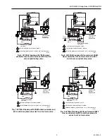
UPPER
SENSING BULB
SENSING BULB AND
ECO SWITCH LOCATION
L8100A
L8100B,C
THERMOCOUPLE
AND PILOT BURNER
MAIN BURNER
M4759
Fig. 3. Location of L8100A,B,C Aquastat® Controllers.


