background image

BACNET® FIXED FUNCTION THERMOSTAT

11

31-00099—01

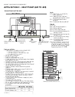
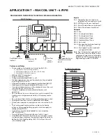
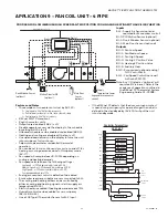
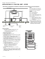
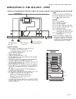
APPLICATION 7 – FAN COIL UNIT – 4 PIPE

Features and Notes

• Three modes of schedule control set by AV-123 –

0 = Single point with offset during occupancy,
1 = Dual setpoint residential – wake, leave, return & sleep,
2 = Dual setpoint with offset occupancy.

• BACnet MS/TP compliant.
• English or metric units.
• Outputs are disabled if BV-2 is off.
• Disable operator access via the display to the schedule 

by setting BV-102 to off.

• Onboard schedule can be enabled or disabled (BV-40).
• Heating and cooling are disabled if the fan is off.
• Use up and down arrows on the display to force the unit 

into occupancy for four hours.

• Setpoint mode emulates residential thermostat 

operation.

• Fan can be set to run continuously or cycle on and off for 

heating or cooling demands while in Occupancy mode 
(AV-17).

• Fan can be either on/off or analog variable speed control.
• Analog economizer control is defaulted to disabled.
• Economizer requires a supply air sensor connected to AI-

2.

• The cooling and heating valves can be controlled by 

either a cooling and heating signal or via the supply air 
temperature (BV-15).

• Humidity control can be enabled for un-occupancy 

(BV-12 & BV-53).

• Use a 10K Type II Thermistor Sensor for AI-2 Input.
• If the BACnet FF detects that the door or window contact 

is open during occupancy for a period longer than what is 
defined in the standby delay (AV-20) it will put the unit 
into standby mode.

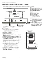
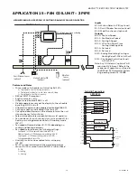
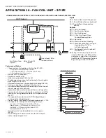
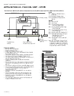
DOOR SENSOR, THREE POINT FLOATING COOLING AND HEATING

Inputs

AI-2:: Supply Air Sensor  (optional, 

required for Economizer control)

BI-0:: PIR Motion Sensor (optional)
BI-1:: Door/Window Sensor (optional)
BI-2:: Main Door Sensor (optional)

Outputs

BO-0:: Fan
BO-1:: Cooling Valve Open
BO-2:: Cooling Valve Close
BO-3:: Heating Valve Open
BO-4:: Heating Valve Close
BO-5:: Not used
AO-0:: Economizer (optional analog) 

0-10V or 4-20mA

AO-1:: Fan Speed Control (optional) 

4-20mA VFD/SCR

Note: Any I/O listed as “optional” will 

require a BV to be set. Refer to the 
sequence of operations outlined in 
the BACnet FF Thermostat System 
Engineering Guide, 31-00098.

MS/TP Network

Digital

3 Point Floating
3 Point Floating

Digital

C
M

Motion Detector PIR

(optional)

Supply 
Temperature Sensor 

(required for economizer 
control) 

Door/Window Sensor 
(optional)

Main Door

Sensor  

(optional)

Fan

C Vlv Op

C Vlv Cl

H Vlv Op

H Vlv Cl

Econ

Controller Terminations     

4PFC AP 7

GND

5

BO 0

BO 1

BO 2

BO 3

BO 4

BO 5

AO 1

Y1

W1

EC

0-10Vdc

Com

14

AO 0

C

RC

1

24V

Com

BI/AI 1

COM

BI/AI 2

COM

BI/AI 0

SA Sensor

Main Door 

Switch

EC/VC

VC

VFD /SCR

4-20ma

Com

G1

G2

G3

Door/Window

Switch

PIR 

Motion

Sensor

4-20ma

Summary of Contents for BACnet

Page 1: ...rm No 31 00096 BACnet Fixed Function Thermostat WEBs AX Configuration Wizard Guide Form No 31 00097 BACnet Fixed Function Thermostat System Engineering Guide Form No 31 00098 TABLE OF CONTENTS Quick Lookup Application Selection Tables 2 Fan Coil Unit 4 Pipe Applications 2 Fan Coil Unit 2 Pipe Applications 2 Heat Pump Applications 3 Air Conditioning Unit Applications 3 Application 0 Heat Pump Air t...

Page 2: ...for Economizer Control Required for Economizer Control Required for Economizer Control Required for Economizer Control Optional Occupancy Detection Optional via Standby Switch Optional Via Door Window Sensors or PIR Optional Via Door Window Sensors or PIR Optional Via Door Window Sensors or PIR Optional Via Door Window Sensors or PIR Condensate Alarm Optional No No No No Application 11 12 13 14 15...

Page 3: ...tional Optional Optional Optional Supply Air Temp Sensor 10K Type II Thermistor Required for Economizer Control Required for Economizer Control Required for Economizer Control Required for Economizer Control Required for Economizer Control Occupancy Detection Optional Via Door Window Sensors or PIR Condensate Alarm Optional Optional Optional Optional Optional Application 4 5 Fan On Off or VFD On O...

Page 4: ...as a sensor set the following parameters SINGLE STAGE ELECTRIC HEAT Inputs AI 0 Space Sensor or Outside Air Sensor optional AI 2 Supply Air Sensor optional required for economizer control BI 1 PIR Door Window Sensor optional BI 2 Condensate Sensor optional Outputs BO 0 Fan BO 1 Heat Pump Compressor BO 2 Reversing Valve BO 3 Electric Heat optional BO 4 Economizer Open optional for floating control ...

Page 5: ...re is water flow To configure AI 0 as a sensor set the following parameters SINGLE STAGE ELECTRIC HEAT Inputs AI 0 Space Sensor or Outside Air Sensor optional AI 2 Supply Air Sensor optional required for economizer control BI 1 PIR Door Window Sensor optional BI 2 Condensate Sensor optional Outputs BO 0 Fan BO 1 Heat Pump Compressor BO 2 Reversing Valve BO 3 Electric Heat optional BO 4 Economizer ...

Page 6: ...ctric heat is enabled when heating demand is 75 To configure AI 0 as a sensor set the following parameters TWO STAGES ELECTRIC HEAT Inputs AI 0 Space Sensor or Outside Air Sensor optional AI 2 Supply Air Sensor optional required for economizer control BI 1 PIR Door Window Sensor optional BI 2 Condensate Sensor optional Outputs BO 0 Fan BO 1 Heat Pump Compressor BO 2 Reversing Valve BO 3 Electric H...

Page 7: ...g demand is 75 Set BV 31 to active by the BMS to indicate that there is water flow To configure AI 0 as a sensor set the following parameters TWO STAGES ELECTRIC HEAT Inputs AI 0 Space Sensor or Outside Air Sensor optional AI 2 Supply Air Sensor optional required for economizer control BI 1 PIR Door Window Sensor optional BI 2 Condensate Sensor optional Outputs BO 0 Fan BO 1 Heat Pump Compressor B...

Page 8: ...65 To configure AI 0 as a sensor set the following parameters COMPRESSOR SINGLE STAGE ELECTRIC HEAT Inputs AI 0 Space Sensor or Outside Air Sensor optional AI 2 Supply Air Sensor optional required for economizer control BI 1 PIR Door Window Sensor optional BI 2 Condensate Sensor optional Outputs BO 0 Fan BO 1 Compressor BO 2 Not used BO 3 Electric Heat optional BO 4 Economizer Open optional for fl...

Page 9: ... Set BV 31 to active by the BMS to indicate that there is water flow To configure AI 0 as a sensor set the following parameters TWO STAGE COMPRESSOR TWO STAGE ELECTRIC HEAT Inputs AI 0 Space Sensor or Outside Air Sensor optional AI 2 Supply Air Sensor optional required for economizer control BI 1 PIR Door Window Sensor optional BI 2 Condensate Sensor optional Outputs BO 0 Fan BO 1 Compressor Stage...

Page 10: ... BV 12 BV 53 Use a 10K Type II Thermistor Sensor for AI 0 and AI 2 Inputs To configure AI 0 as a sensor set the following parameters THREE POINT FLOATING COOLING AND HEATING Inputs AI 0 Space Sensor or Outside Air Sensor optional AI 2 Supply Air Sensor optional required for economizer control BI 1 PIR Door Window Sensor optional BI 2 Condensate Alarm optional Outputs BO 0 Fan BO 1 Cooling Valve Op...

Page 11: ...Use a 10K Type II Thermistor Sensor for AI 2 Input If the BACnet FF detects that the door or window contact is open during occupancy for a period longer than what is defined in the standby delay AV 20 it will put the unit into standby mode DOOR SENSOR THREE POINT FLOATING COOLING AND HEATING Inputs AI 2 Supply Air Sensor optional required for Economizer control BI 0 PIR Motion Sensor optional BI 1...

Page 12: ...y air temperature BV 15 Humidity control can be enabled for un occupancy BV 12 BV 53 Use a 10K Type II Thermistor Sensor for AI 2 Input If the BACnet FF detects that the door or window contact is open during occupancy for a period longer than what is defined in the standby delay AV 20 it will put the unit into standby mode DOOR SENSOR LOW MEDIUM HIGH SPEED FAN TWO POSITION COOLING AND HEATING Inpu...

Page 13: ...demand exceeds 75 Humidity control can be enabled for un occupancy BV 12 BV 53 Use a 10K Type II Thermistor Sensor for AI 2 Input If the BACnet FF detects that the door or window contact is open during occupancy for a period longer than what is defined in the standby delay AV 20 it will put the unit into standby mode DOOR SENSOR LOW MEDIUM HIGH SPEED FAN TWO POSITION COOLING AND HEATING WITH AUXIL...

Page 14: ...53 Use a 10K Type II Thermistor Sensor for AI 2 Input If the BACnet FF detects that the door or window contact is open during occupancy for a period longer than what is defined in the standby delay AV 20 it will put the unit into standby mode To configure AI 0 as a sensor set the following parameters SINGLE STAGE ELECTRIC HEAT AND 3 SPEED FAN Inputs AI 0 Space Sensor or Outside Air Sensor optional...

Page 15: ...10K Type II Thermistor Sensor for AI 2 Input If the BACnet FF detects that the door or window contact is open during occupancy for a period longer than what is defined in the standby delay AV 20 it will put the unit into standby mode LOW MEDIUM HIGH SPEED FAN THREE POINT FLOATING OR ANALOG COOLING OR HEATING REMOTE SPACE TEMPERATURE SENSOR Inputs AI 2 Space Temp Sensor optional BI 0 Motion Detecto...

Page 16: ...nabled for un occupancy BV 53 If the BACnet FF detects that the door or window contact is open during occupancy for a period longer than what is defined in the standby delay AV 20 it will put the unit into standby mode DOOR SENSOR LOW MEDIUM HIGH SPEED FAN THREE POINT FLOATING OR ANALOG COOLING OR HEATING Inputs BI 0 Motion Detector PIR optional BI 1 Door Window Sensor optional BI 2 Main Door Sens...

Page 17: ...trol can be enabled for un occupancy BV 53 Use a 10K Type II Thermistor sensor for the strap on water supply temperature DOOR SENSOR LOW MEDIUM HIGH SPEED FAN THREE POINT FLOATING OR ANALOG COOLING OR HEATING AND ELECTRIC HEATER Inputs BI 0 Motion Detector PIR optional BI 1 Door Window Sensor optional AI 2 Supply Water Temperature Sensor Outputs BO 0 Fan Low Speed BO 1 Fan Medium Speed BO 2 Fan Hi...

Page 18: ... set at 2 Humidity control can be enabled for un occupancy BV 53 Use a 10K Type II Thermistor sensor for the strap on water supply temperature WATER TEMP SENSOR LOW MEDIUM HIGH SPEED FAN TWO POSITION OR ANALOG COOLING OR HEATING Inputs BI 0 Motion Detector PIR optional BI 1 Door Window Sensor optional AI 2 Supply Water Temperature Sensor Outputs BO 0 Fan Low Speed BO 1 Fan Medium Speed BO 2 Fan Hi...

Page 19: ... speed deadband set at 2 Humidity control can be enabled for un occupancy BV 53 AV 23 is used to determine if the water temperature sensor AV 15 sourced from the BMS is to be utilized 0 No 1 cooling 2 heating LOW MEDIUM HIGH SPEED FAN 2 POSITION OR ANALOG COOLING OR HEATING Inputs BI 0 Motion Detector PIR optional BI 1 Door Window Sensor optional BI 2 Main Door Sensor optional Outputs BO 0 Fan Low...

Page 20: ... 2 Humidity control can be enabled for un occupancy BV 53 Use a 10K Type II Thermistor sensor for the strap on water supply temperature LOW MEDIUM HIGH SPEED FAN 2 POSITION OR ANALOG COOLING OR HEATING AND ELECTRIC HEAT Inputs BI 0 Motion Detector PIR optional BI 1 Door Window Sensor optional AI 2 Supply Water Temperature Sensor Outputs BO 0 Fan Low Speed BO 1 Fan Medium Speed BO 2 Fan High Speed ...

Page 21: ...the supply air temperature BV 15 Humidity control can be enabled for un occupancy BV 12 BV 53 Use a 10K Type II Thermistor Sensor for AI 2 Input To configure AI 2 as a sensor set the following parameters PIR SENSOR ANALOG COOLING AND HEATING THREE POINT FLOATING ECONOMIZER Inputs AI 2 Space Temperature Sensor Optional or could be a Supply Air Temperature Sensor required for economizer control BI 0...

Page 22: ...POSITION THREE POINT FLOATING OR ANALOG COOLING OR HEATING VALVE ELECTRIC HEATER ON OFF OR VFD FAN Inputs BI 1 PIR Door Window Sensor optional AI 0 Supply Air Temperature AI 2 Supply Water Temperature Sensor Outputs BO 0 Fan On Off BO 1 Not Used BO 2 Cooling Heating Valve 2 Position Open Close BO 3 Cooling Heating Valve Open 3 Point Floating BO 4 Cooling Heating Valve Close 3 Point Floating BO 5 A...

Page 23: ...ll CC AV 26 12 1 to 1440 AC HP Compressor Cycle Time mins 0 3 10 C0 AV 27 3 AC HP Compressor Minimum On Runtime mins 0 3 10 CF AV 18 3 AC HP Compressor Minimum Off Runtime mins 0 3 10 Hc AV 28 3 1 to 1440 Heating Stages Cycle Time mins if set to 0 or less this will disable heating 0 5 9 10 13 16 18 h0 AV 29 1 Heating Stages Minimum runtime mins 0 5 9 10 13 16 18 hF AV 80 60 Heating Stages Minimum ...

Page 24: ...HP Comressor App 10 AV 41 Heat Signal Proportional Gain AV 87 Runtime Cooling Stage 1 AV 42 Heating Signal Integral Gain AV 88 Runtime Cooling Stage 2 AV 43 Cool Signal Proportional Gain BV 21 Reverse Valve Action 1 cool AV 44 Cooling Signal Integral Gain BV 22 1 Cooling Locked Out AV 57 Calc Compr Off time sec BV 27 1 Heating Locked Out AV 58 Calc Compr Cycle time sec BV 6 HP Fun Request AV 59 Ca...

Page 25: ...BACNET FIXED FUNCTION THERMOSTAT 25 31 00099 01 ...

Page 26: ...BACNET FIXED FUNCTION THERMOSTAT 31 00099 01 26 ...

Page 27: ...BACNET FIXED FUNCTION THERMOSTAT 27 31 00099 01 ...

Page 28: ...utomation and Control Solutions Honeywell International Inc 1985 Douglas Drive North Golden Valley MN 55422 customer honeywell com U S Registered Trademark 2016 Honeywell International Inc 31 00099 01 M S 05 16 Printed in United States ...

Reviews: