Appendix
BC-200 Manual
– P/N DOC-01-013
100
9.3.2.6
P
ROGRAMMING
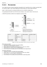
The LCD80 annunciator mode pre-programmed messages can be programmed in via a laptop using the BC-200
PC Interface Program. Each required message must be activated via a script in the BC-200 panel.
Switch 7 of DIP switch SW1 will enable the RS232 port on the LCD80 for programming.
The upload/download cable for the LCD-80 is a 9 pin female on one end and 3 wires on the other end.
A RS-232 serial cable is needed in the configuration as shown below:
LCD-80
EIA Name
9 PIN Connector
25 PIN Connector
1
Tx D
3
2
6
Signal Ground
5
7
7
Rx D
2
3
No Connection
DTR
4 (Note 1)
20
No Connection
DSR
6 (Note 1)
6
Note 1:
Pin 4 (DTR) is connected to pin 6 (DSR) in the 9 pin connector housing.
Downloading new labels:
Using the PCI create an LCD-80 at the desired address.
Enter all the required descriptors in the PCI.
Set dip switch 7 to on and connect the programming cable to the LCD-80.
Select download on the PCI and tick the LCD-80 option.
The PCI will ask for the address of the LCD-80 before commencing download.
Uploading existing labels:
Using the PCI create an LCD-80 at the desired address.
Set dip switch 7 to on and connect the programming cable to the LCD-80.
Select upload on the PCI and tick the LCD-80 option.
The PCI will ask for the address of the LCD-80 before commencing upload.
Summary of Contents for BC-200
Page 1: ...BC 200 OPERATION INSTALLATION PROGRAMMING MANUAL P N DOC 01 013 ECN11 0058 23 Aug 12 Rev 5 07 ...
Page 138: ...Appendix BC 200 Manual P N DOC 01 013 138 9 12 PANEL EXPANSION RELAYS ...
Page 142: ...Appendix BC 200 Manual P N DOC 01 013 142 9 9 1 13 3 4 4 R RE EL LA AY Y M MO OD DU UL LE E ...
Page 144: ...Appendix BC 200 Manual P N DOC 01 013 144 9 9 1 13 3 6 6 Z ZO ON NE E M MO OD DU UL LE E ...
Page 155: ......

