Appendix
BC-200 Manual
– P/N DOC-01-013
116
9
9
.
.
6
6
.
.
4
4
A
A
N
N
A
A
L
L
O
O
G
G
L
L
C
C
M
M
A
A
N
N
D
D
L
L
E
E
M
M
T
T
E
E
R
R
M
M
I
I
N
N
A
A
T
T
I
I
O
O
N
N
S
S
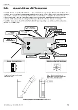
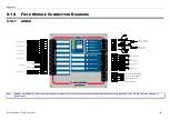
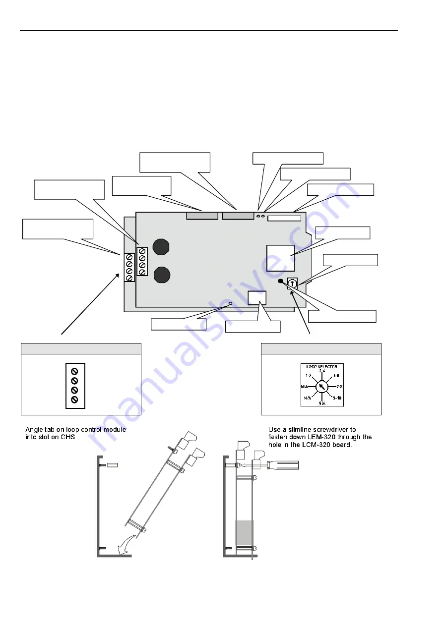
The LCM-320 and the updated ELCM-320 is a 1-loop board that can support up to 99 detectors and 99 modules
in CLIP mode. The field wiring is electrically isolated from the rest of the system so that any two-ground faults on
separate loops will not cause invalid replies from devices. A short to any other system circuit will not cause
communication loss. The LCM has an earth fault detection circuit with a yellow LED displaying an earth fault
condition. ELCM modules also include a green heartbeat LED to show that the processor is working.
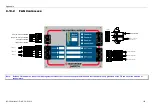
The LEM is an expansion board that attaches to its LCM parent providing a second loop which has the same
features as the parent loop.
MicroController
Connector to LEM
Ground Fault on LCM
20 Way Ribbon to
next LCM
20 Way Ribbon From
LIM or Previous LCM
Address Switch
Ground Fault on LEM
LCM Firmware
5VDC OK
First Loop
(Loops 1, 3, 5, 7, 9)
Second Loop
(Loops 2, 4, 6, 8, 10)
Heartbeat LED (ELCM)
Loop Connections
Address Switch Settings
A-
B-
A+
B+
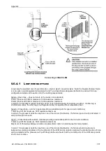
Inserting a pair of LCM/LEM into CHS-3L/4L
Summary of Contents for BC-200
Page 1: ...BC 200 OPERATION INSTALLATION PROGRAMMING MANUAL P N DOC 01 013 ECN11 0058 23 Aug 12 Rev 5 07 ...
Page 138: ...Appendix BC 200 Manual P N DOC 01 013 138 9 12 PANEL EXPANSION RELAYS ...
Page 142: ...Appendix BC 200 Manual P N DOC 01 013 142 9 9 1 13 3 4 4 R RE EL LA AY Y M MO OD DU UL LE E ...
Page 144: ...Appendix BC 200 Manual P N DOC 01 013 144 9 9 1 13 3 6 6 Z ZO ON NE E M MO OD DU UL LE E ...
Page 155: ......

