Appendix
BC-200 Manual
– P/N DOC-01-013
120
9
9
.
.
6
6
.
.
5
5
N
N
E
E
T
T
W
W
O
O
R
R
K
K
I
I
N
N
G
G
BC-200 Networking is accomplished using a series of modules and products which allow a group of Fire Alarm
Control Panels (FACP) and other control equipment to connect, forming a true peer-to-peer network. Equipment
that connects to network and communicates with other equipment using the network may be referred to as a
network node. The minimum hardware requirement for network is two nodes connected via wire (or optical fibre).
Network for the BC-200 supports up to 100 nodes. The BC-200 occupies a single node address on the network.
Each network node requires a unique node address; the node communicates with other nodes via a Network
Control Module (NCM)
.
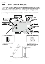
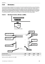
The NCM connects to the BC-200 via the Network Interface Module (NIM).
9.6.5.1
N
ETWORK
I
NTERFACE
M
ODULE
(NIM)
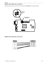
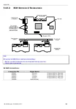
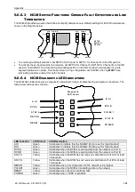
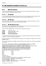
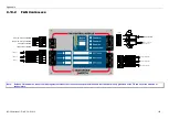
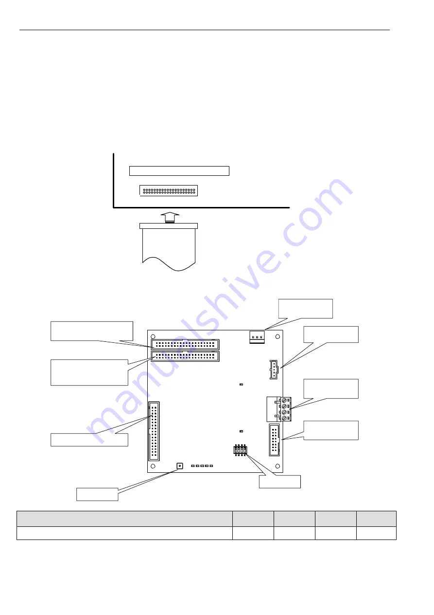
To Network Interface Module
40 WAY
RIBBON
CABLE
MAIN
TERMINATION BOARD (FIM)
J3
Ribbon cable to LIM (If fitted)
Ribbon cable from FIM
(termination board)
Power connector
f rom FIM ( termination
board)
NCM connection
(NUP port on IFS-725)
Not used on NIM
20 Way ribbon cable
to LCM/LEM boards
Factory programming port
Reset Switch
Address Switch
Address Settings
SW1
SW2
SW3
SW4
Network Interface Module
ON
ON
OFF
OFF
NIM connects to the NUP port on the NCM.
Summary of Contents for BC-200
Page 1: ...BC 200 OPERATION INSTALLATION PROGRAMMING MANUAL P N DOC 01 013 ECN11 0058 23 Aug 12 Rev 5 07 ...
Page 138: ...Appendix BC 200 Manual P N DOC 01 013 138 9 12 PANEL EXPANSION RELAYS ...
Page 142: ...Appendix BC 200 Manual P N DOC 01 013 142 9 9 1 13 3 4 4 R RE EL LA AY Y M MO OD DU UL LE E ...
Page 144: ...Appendix BC 200 Manual P N DOC 01 013 144 9 9 1 13 3 6 6 Z ZO ON NE E M MO OD DU UL LE E ...
Page 155: ......


