Panel Operation
BC-200 Manual
– P/N DOC-01-013
22
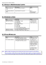
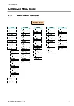
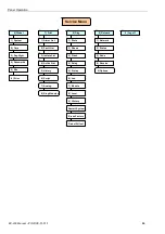
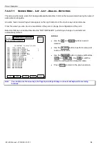
System points will be displayed and can be referred to as follows:
Description
Syntax
Comments
On Board AZF’s
2 AZF’s on termination Board
AZF #1
0.1.Z1
Ring 0 Module 1, zone 1
AZF #2
0.1.Z2
Ring 0 Module 1, zone 2
On Board Relays
8 Relays on termination Board
Relay 1 to 8 on FIM
0.4.O1 to 0.4.O8
Ring 0 Module 4, output 1
Ring 0 Module 4, output 8
Distributed Field Modules
Up to 100 modules
AZF
1.1.Z1
8 AZF points per AZM8module
Din
1.1.I1
3 Din Per Fan Control Module
Dout
1.1.O1
4 Dout Per AZM-8
3 Dout Per Fan Control Module
Description
Syntax
Comments
Annunciator
Up to 50 Annunciators
Inputs
1.101.I1
16 Din per 16AT, 24 Din Per SCS-8
Outputs
1.101.O1
32 Dout Per 16AT, 24 Dout Per SCS-8, 32
Dout Per ACM32A
Analog Addressable Devices
Up to 4 Loops
Detectors
L1D1
99 Detectors Per Loop
Modules
L1M1
99 Modules Per Loop
Virtual Points
VPn
n can range up to 1000
Network Points
NPn
n can range up to 1000
Expansion Relays
XRn
n can range up to 64
System Parameters
Common Alarm
CA
Common Fault
CF
Common Isolate
CI
Battery Fault
BF
Charger Fault
CL
Mains On
MO
Ext. Bell Isolated
BI
Warning System Isolated
WI
Summary of Contents for BC-200
Page 1: ...BC 200 OPERATION INSTALLATION PROGRAMMING MANUAL P N DOC 01 013 ECN11 0058 23 Aug 12 Rev 5 07 ...
Page 138: ...Appendix BC 200 Manual P N DOC 01 013 138 9 12 PANEL EXPANSION RELAYS ...
Page 142: ...Appendix BC 200 Manual P N DOC 01 013 142 9 9 1 13 3 4 4 R RE EL LA AY Y M MO OD DU UL LE E ...
Page 144: ...Appendix BC 200 Manual P N DOC 01 013 144 9 9 1 13 3 6 6 Z ZO ON NE E M MO OD DU UL LE E ...
Page 155: ......

